


B KLN 94
Rev. 4, Jan/2003 10599I04.CDL Page 2-5
2.3.6.2 Functional Pinout Descriptions
This section gives a brief description of some of the inputs and outputs of the KLN 89/89B. It is
provided so the installer can determine what specific wiring needs to be done to the aircraft in
which the unit is to be installed. Unless otherwise specified, pins not used are to be left open.
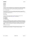
CONNECTOR P941
Pin 1; GENERAL RS 232 IN
Pin 1 is the RS 232 input. The KLN 94 must be configured correctly for the type of equipment (or
no equipment) connected to this input. Refer to Section 2.4.1 for the configuration procedure.
It is not necessary to connect this input to the GENERAL RS 232 OUT when this input is not
used as the “No Fuel Mgt Sys” and “No Air Data” configuration choices indicate this input is
unused and inhibit the “No RS-232 Data” message. For specific label information, refer to RS 232
Format Definitions Appendix.
Pin 2; GENERAL RS 232 OUT
The KLN 94 outputs data in RS 232 format on this pin. It can be used to interface with certain
types of ELT’s, fuel sensors, moving map displays, and fuel management systems. For specific
label information, refer to RS 232 Format Definitions Appendix.
Pin 3; DATA LOADER RS 232 IN
Pin 3 inputs Data Loader information in RS 232 format. It can be used to interface with a laptop
IBM compatible PC to load the database.
Pin 4; DATA LOADER/QUICKTUNE
TM
RS 232 OUT
Pin 4 outputs Data Loader information in RS 232 format. It can be used to interface with a laptop
IBM compatible PC to load the database and to quick-tune some VHF COMM units..
Pin 5; SPARE RS 232 IN
Pin 5 is a spare RS 232 input.
Pin 6; GPS SENSOR RS 232 OUT
Pin 6 is a GPS Sensor RS 232 output; Typically used for RPGWS interface.
Pin 7; OBI SYNC
Pin 8; OBI CLOCK
Pin 9; OBI DATA
This is a three wire data bus that provides bearing to the active waypoint. The data is in
Honeywell format and can be used to drive certain Honeywell RMI units.