


B KLN 94
Rev. 4, Jan/2003 10599I04.CDL Page 1-13
1.6.3 NAV/GPS Switching
Installations in which the outputs from a KLN 94 and an existing navigation system are being
switched onto a common indicator will require some remote relay switching that is controlled by
the NAV/GPS switch/annunciator.
1.6.4 Right Angle Connector
The part number for a right angle connector for the KA 91 or KA 92 antenna connection is
030-00134-0001. This right angle connector was originally an option but has been included in the
installation kit as the standard connector.
1.7 LICENSE REQUIREMENTS
None.
1.8 RECOMMENDATIONS FOR IFR APPROVAL
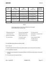
1.8.1 Aircraft Logbook Entry
1.8.2 Aircraft Installation Requirements
NOTE
For the following subsections, refer to Section 1.5 and Section 1.6
for allowable configurations where applicable. Refer to Section II for
illustrations.
1.8.2.1 TSO/JTSO’d Antenna
The antenna must be a TSO/JTSO’d KA 91, P/N 071-01545-0200 or KA 92 P/N
071-01553-0200. If the P/N of the KA 91 is not available, it may be identified by the serial number
as the TSO/JTSO’d antennas have a five digit serial number.
1.8.2.2 Nav Instrumentation
The navigation information (D-Bar, Nav Flag, and To-From) must be displayed on an instrument
in the pilot’s panel. Electromechanical indicators are capable of displaying the variable scale
factors of enroute, terminal, and approach modes.
1.8.2.3 OBS Interface
The use of an OBS resolver will reduce pilot workload during an instrument approach. It allows
the OBS setting to be changed on the navigation indicator when the KLN 94 is operating in the
OBS mode. Without the OBS resolver connection, the OBS may be changed from the KLN 94
controls. OBS mode is commonly used during procedure turns and holding patterns.
Some certification agencies may require the use of the OBS resolver for approach certification.
Consult your approval agency for additional information. Refer to Section 1.3 and Section 2.3.6
for additional OBS information.