


B KLN 94
Rev. 4, Jan/2003 10599I04.CDL Page 2-2
In the case of the KLN 94, installation of a KA 33, (P/N 071-4037-XX), or equivalent cooling
system is required. Ram air cooling is not acceptable. For installation information on the KA 33
refer to the KA 33 installation manual, P/N 006-01069-XXXX or Installation Bulletin 258.
2.3.2 KLN 94 MECHANICAL INSTALLATION
The KLN 94 installation will conform to standards designated by the customer, installing agency,
and existing conditions as to the unit location and type of installation. However, the following
suggestions will assure a more satisfactory performance from the equipment.
A. Plan a location on the aircraft panel so that the KLN 94 is plainly visible to the pilot and so that
he has complete access to all front panel controls. Check to be sure that there is adequate depth
behind the panel for the mounting rack and all the connectors and cabling. Be sure that the
mounting location is not close to heater vents or other sources of high heat.
B. Refer to figure 2-3 for the panel cutout dimensions. Mark and cut the panel opening.
2.3.3 ANTENNA SELECTION
The KA 91 and KA 92 GPS active antennas, P/N 071-01545-0200 and 071-01553-0200
respectively, are the designated antennas for the KLN 94.
2.3.4 ANTENNA INSTALLATION CONSIDERATIONS
The antenna should be mounted on top of the fuselage near the cockpit. Avoid mounting the
antenna near any projections, the propeller, and the T-tail of the aircraft, where shadows could
occur. It is recommended that there be a separation of at least 3 ft between the KLN 94 GPS
antenna and any VHF Comm antenna on the aircraft. Antenna baseplate must be level within
± 5° in both axes when the aircraft is in level flight. If the antenna is tilted more than 5° or is
mounted close to other objects that shadow it, loss of some of the satellites will occur and system
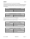
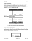
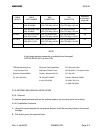
performance may be degraded. Antenna cable and connector information, including vendor
information, is listed below. Refer to figure 2-10 (TNC) and figure 2-11 (BMA) for cable/connector
assembly instructions for the 0 to 40 feet category using RG 400/U or RG 142B/U. Refer to
Figure 2-12 (for both TNC and BMA) for the 0 to 80 feet and 0 to 100 feet categories.
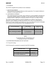
NOTE
KA 91/92 nominal gain and noise figures are 26.5 dB and 2.3 dB
respectively. With 0.050 ice on radome, gain will not decrease by
more than 2.0 dB when viewing a satellite from 30° above the
horizon to zenith, as compared to a no ice condition.