


B KLN 94
Rev. 4, Jan/2003 10599I04.CDL Page 2-8
If the installation is approved for approach and the external switch/annunciator is installed, then a
momentary ground on pin 8 will alternately arm or disarm the approach mode.
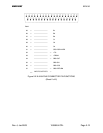
Pin 9; LATERAL SUPER FLAG
Pin 10; VERTICAL SUPER FLAG
On superflag outputs, a logic high shall be
≥ 18 VDC when the voltage at pin 19 is ≥ 24.8 VDC. A
logic high shall be
≥ 10 VDC when the voltage at pin 19 is ≥ 12.4 VDC. A logic high shall be ≥ 20
VDC when the voltage at pin 19 is + 27.5 VDC. A logic low shall be
≤ 3.5 VDC.
Pin 11; LATERAL DEV +L
Pin 12; LATERAL DEV +R
Pin 13; VERTICAL DEV +UP
Pin 14; VERTICAL DEV +DOWN
These pins are deviation outputs and function as differential pairs. For the specifications on these
outputs, refer to Section 1.3 of this manual.
Pin 15; ALTITUDE ALERT AUDIO
Pin 16; ALTITUDE ALERT AUDIO LO
These pins represent the Altitude Alert Audio output, which is active whenever ALTITUDE ALERT
ANNUNCIATE is active.
Pin 17; FCS LOC ENG
This annunciator is active when the lateral deviation scale factor is 0.3 nm. It is also active while
the scale is transitioning from 1.0 nm down to 0.3 nm.
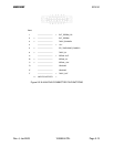
Pin 18; A/C POWER MONITOR
Pin 18 is the aircraft power monitor. It senses voltages ranging from 0 to 33 V. The KLN 94 can be
configured to allow the selection of a voltage alert set point and a voltage alert delay interval for
use with this input. Refer to Section 2.4.1 for the configuration procedure. The “Low Bus Voltage,
Check Charging System” message is displayed when voltage at this pin is below the voltage alert
set point for greater than the voltage alert delay interval.
Pin 19; 11-33 VDC A/C POWER
Pin 19 is the DC aircraft power input. The KLN 94 will accept from 11 VDC to 33 VDC input
power.
Pin 20; A/C GROUND
Pin 20 is tied to aircraft ground. Wiring harness shields are not to be terminated on this pin. Refer
to Figure 2-17.
Pin 21; D4
Pin 22; A1
Pin 23; A2
Pin 24; A4