


B KLN 94
Rev. 4, Jan/2003 10599I04.CDL Page 1-2
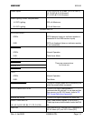
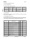
Power Inputs: 11 to 33 VDC at 3.0 A Max. (-20°C to +55°C)
13.75 VDC @ 2.5 A Nominal
27.5 VDC @ 1.25 A Nominal
Panel Lighting Current Requirements:
14 VDC Lighting:
28 VDC Lighting:
220 mA Maximum
110 mA Maximum
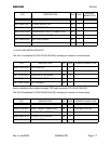
SIGNAL INPUTS
GPS DISPLAYED:
OPEN:
GND
GPS displayed (when an indicator resolver is
connected to the OBS resolver inputs)
GPS not displayed (when an indicator resolver
is not connected)
TAKE HOME
:
OPEN:
GND:
Normal Operation
Take Home Mode
SPARE IN 0:
These are reserved pins
for future use.
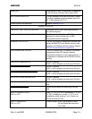
SPARE IN 1:
SPARE IN 2:
SPARE IN 3:
TEST:
OPEN:
GND:
Normal Operation
Test Mode
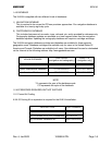
APPROACH ARM IN
: This pin is normally open with a momentary low
while the panel button is pressed.
DATA LOADER RS 232 IN: This RS 232 input is designated to
communicate with devices, ie. air data and fuel
flow sensors via RS 232 format. (refer to RS
232 Format Definitions Appendix)
SPARE RS 232 IN: This RS 232 input is reserved for future use.
GRAY CODE INPUTS:
(A1, A2, A4, B1, B2, B4, C1, C2, C4, D4)
Gray Code Altitude Signals. (0 to 28 VDC)
These inputs are diode isolated inside the KLN
94.
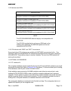
OBS SIN: OBS resolver sine. Nominal input impedance is
33.8 K ohms (AC) and 100 K ohms (DC)