


B KLN 94
Rev. 4, Jan/2003 10599I04.CDL Page 2-4
C. Use a piece of fine sandpaper or emery cloth to sand the area on the fuselage skin on which
the doubler plate for the antenna is to be mounted and on the aircraft skin under where the
antenna will be mounted.
D. Apply Alumiprep No. 33, P/N 016-01127-0000, to both the inside and outside areas of the
fuselage and to the back of the doubler plate. Follow the directions on the container to
cleanse the metal of any left over residue.
E. Apply Alodine, P/N 016-01128-0000, to both locations following the directions on the
container. This is used to ensure good bonding of the antenna and to prevent oxidation.
F. Refer to Figure 2-5 for the KA 91 installation drawing or Figure 2-8 for the KA 92 installation
drawing and mount the antenna as shown. First rivet the doubler plate in place. It is
imperative that the doubler plate make a good electrical bond with the inside of the aircraft
skin and that the antenna itself be well bonded to the aircraft.
G. When installing the KLN 94 antenna (KA 91/KA 92) do not exceed 50 inch/lbs of torque on
the antenna mounting screws.
H. Apply a bead of sealant around the base of the antenna and seal the antenna mounting
screw holes to prevent water damage.
2.3.6 ELECTRICAL INSTALLATION
2.3.6.1 General Information
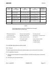
The KLN 94 will operate with an input voltage from 11 to 33 VDC but the front panel lighting
circuit must be wired for either +14 VDC or +28 VDC, depending upon the aircraft lighting bus.
Refer to the KLN 94 interconnect diagram for wiring details.
A. The installing facility will supply and fabricate all external cables. The required connectors are
supplied as part of the installation kit.
B. The length and routing of the external cables must be carefully planned before attempting the
actual installation. Avoid sharp bends or locating the cable near aircraft control cables.
C. The KLN 94 and associated wiring must be kept at least a minimum of 3 ft. from high noise
sources and not routed with cables from high power sources to insure optimum performance
from the system.
D. Do not route the antenna cable near any cable used for a transmitting antenna. Prior to
installing the KLN 94 itself, a point to point continuity check of the wiring harness should be
done to verify proper wiring. The aircraft power input to the unit should be made to insure that
power is applied to only the specified power pin(s).