


Interfacing formats are selected from the Setup options, described on page 87.
The input/output lines on your GPS III Pilot are RS-232 compatible allowing easy
interface to a wide range of external devices, including PCs, differential
beacon receivers, marine autopilots and/or a second GPS receiver.
The NMEA 0183 version 2.0 interface format is supported by the
GPS III Pilot and enables the unit to drive up to three NMEA devices:
NMEA 0183 version 2.0 Approved sentences:
GPGGA, GPGLL, GPGSA, GPGSV, GPRMB, GPRMC, GPRTE,
GPWPL, GPBOD
Proprietary sentences:
PGRME (estimated error), PGRMM (map datum), PGRMZ
(altitude), PSLIB (beacon receiver control)
DGPS (Differential GPS) corrections are accepted in RTCM SC-104
version 2.0 format through the Data In line. The GARMIN GBR 21 is the
recommended beacon receiver for use with the GPS III Pilot. Other beacon
receivers with the correct RTCM format may be used, but may not correct-
ly display status or allow tuning control from the GPS unit.
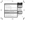
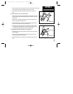
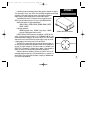
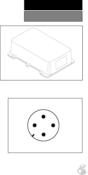
The GPS III Pilot may be hard-wired to a vehicle’s electrical system (10-
32 VDC) using an optional power/data cable. Consult the wiring diagram to
the right for proper connections. (The male connector on the back of the
GPS III Pilot is illustrated.) A cigarette lighter adapter is also available to
power your GPS III Pilot without making permanent connections.
Additional cables are available to connect your GPS III Pilot to a PC-
compatible computer’s serial port (PC Interface Cable) or to connect to a
second GPS III Pilot (Data Cross-Load Cable). Contact your GARMIN deal-
er for any of these accessories.
91
GARMIN
GBR 21
(+) Power
(-) Ground
Data In Data Out
GPS III Pilot Connections (from back of unit)
GARMIN GBR 21 Beacon Receiver
APPENDIX C
Wiring / Interfacing
GPS III Pilot B2 4/1/99 2:02 PM Page 91