


12. INSTALLATION
12-4
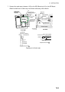
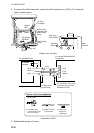
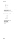
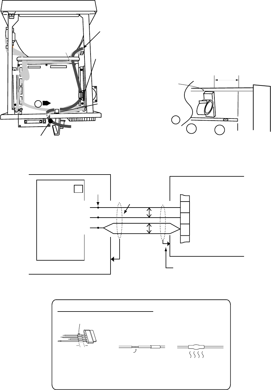
8. To connect the AIS transponder, connect the NH connector assy. (5P) to J2, routing the
cable as shown below.
From AIS
J103
J105
J104
J214
J102
SPU Board
03P9230
J101
Attach clamp
(supplied) and
pass through
clamp.
A
Pass through
clamp.
To J2 on
RP Board
Square
Hole
Rear
Chassis
30 mm
Align flush
with chassis.
Exploded
view of A
Solder
Display unit, top view
20 mm
(1) Cut shrink tubing
in 20 mm lengths and
slip onto each wire.
(3) Heat shrink
tubing with
soldering iron.
Shrink tubing
(2) Solder connector
to signal cable.
Solder
HOW TO ATTACH NH CONNECTOR
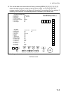
RP BOARD
14P0390A
RD-A
> 3 >
RD-B
> 4 >
GND
> 5 >
FA-100 AIS TRANSPONDER
Junction Box
J2
FR-1500 MKIII Series
Solder
Armor
*
25
26
27
TD-A
TD-B
GNDiso
*
* = Clamp armor
by cable clamp.
Use JIS cable TTYCS-1Q or
equivalent. (See FA-100's
installation manual.)
Pair
Pair
Connection of AIS
9. Reattach the display unit cover.