B–4
Output signal (contact closure signal)
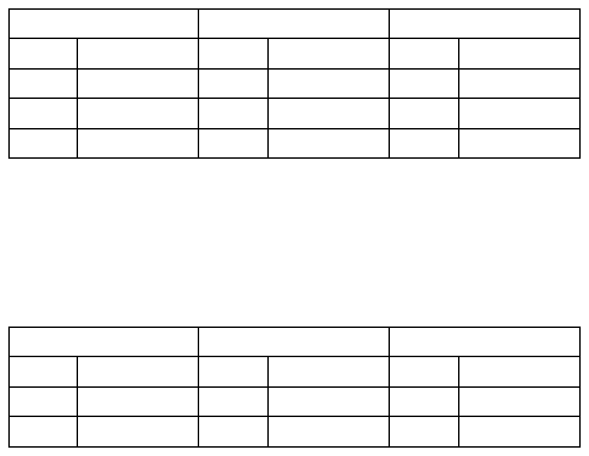
J10 (WPT alarm) J11 J12
Pin no. Designation Pin no. Designation Pin no. Designation
#1 Alarm signal #1 Alarm signal #1 Alarm signal
#2 Alarm signal #2 Alarm signal #2 Alarm signal
#3 GND #3 GND #3 GND
Selection of output data format
The output data format is selectable by changing a jumper block; A for RS-422 and B for
NMEA. For example, to select NMEA for J4, change the jumper block from A to B on J401
and J402. Do the same on J5 thru J9.
J10 (WPT alarm) J11 J12
Output Jumper Output Jumper Output. Jumper
J4 J401/J402 (A) J5 J501/J502 (A) J6 J601/J602 (A)
J7 J701/J702 (A) J8 J801/J802 (A) J9 J901/J902 (B)
Default of jumper setting is shown in parenthesis.
Maintenance
Fuse replacement
If the fuse blows, find the cause of the problem before replacing it. Do not use a fuse rated
more than 0.5A, since it may cause more serious damage to the equipment.
Self test 1
The unit performs an internal self-check in the following sequence each time power is turned
on.
1) LEDs CR7 to CR10 blink twice every 2 seconds.
2) ROM and RAM are tested.
3) LED CR13 blinks every second for normal operation. If an error is detected during the
test, the corresponding LED is turned on.
• When CR7 is on, ROM is defective.
• When CR8 is on, RAM is defective.


