


C-15
• Load Requirements
Isolation: opto coupler
Input Impedance: 470
Ω
Max. Voltage:
±
15V
Threshold: 3mA (In case of FURUNO device talker connection)
• Input Sentence is described on page C-11.
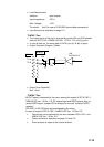
"DATA3" Port
• The output signal of this port is changed by jumper JP4 and JP5 between
data out (IEC 61162-1/NMEA 0183 Ver.
1.5/Ver. 2.0) and log pulse.
• In case of data out, the same data of DATA1 port (#1 & #2) is output.
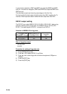
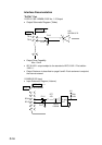
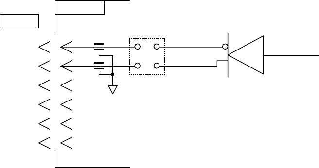
• Output Schematic Diagram (Talker)
20P8147
MJ-A6SRMD
14
13
12
1
3
2
4
DATA3
1
J6
2
3
4
5
6
FL5
FL6
JP4
TD-A
TD-B
U35
SN75ALS172
• Output Drive Capability
Max. 10mA
"DATA4" Port
IN/OUT signal is selected by the menu among the output of IEC 61162-1,
NMEA 0183 Ver. 1.5/Ver. 2.0, PC output/input and DGPS signal. Also, to
select DGPS signal, jumper JP3 is required to connect "external DGPS
receiver."
RS-232C or RS-422 level can be selected by the menu.
In case of output of IEC 61162-1, NMEA 0183 Ver. 1.5/Ver. 2.0,
• Data format can be selected by the menu between IEC 61162-1 and
NMEA 0183 Ver. 1.5/Ver. 2.0.
• Output sentence is described on page C-8 and C-9.
• Each sentence is output at the interval entered.