


2-38 / Installation & Operation CI-ControlWave EFM
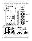
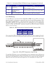
Table 2-11 - Non Isolated Mixed I/O Module Jumper Assignments (Continued)
Jumper Purpose Notes
W23 - W26
Configures AI1 through AI4
(respectively)
Pins 1-2 installed = 4-20mA AI (250 ohm resistor
in)
Pins 2-3 installed = 1-5V AI
W27
AO Voltage Selection
Set W27 Pins 2-3
ALWAYS
Pins 1-2 installed = N/A
Pins 2-3 installed = External Field Voltage (TB2-9)
W28 HSC Circuitry Enable
Pins 1-2 installed = HSC Circuit Enable (Powered)
Pins 2-3 installed = HSC Circuit Disabled
* = W1 located on optional AO Daughter Board
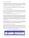
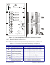
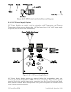
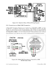
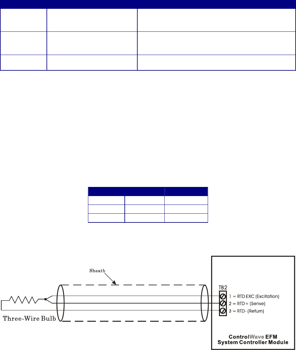
2.3.5 RTD Wiring
A 3-wire RTD may be provided with the ControlWave EFM. Connector TB2 on the System
Controller Module accommodates a removable three-wire Terminal Block (similar to TB1).
This connector accommodates a 100-ohm platinum bulb using the DIN 43760 curve.
ControlWave EFM’s utilize the common three-wire configuration. In this configuration,
the Return lead connects to RTD- and the two junction leads (Sense and Excitation),
connect to RTD+ and RTD EXC. Connection between the RTD and System Controller
Module is wired as follows:
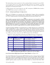
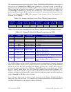
Table 2-12 - RTD Connections to System Controller Connector TB2
TB2 Pin
Signal Function
1 RTD EXC Excitation
2 RTD+ Sense
3 RTD- Return
Never ground the RTD Cable Shield at both ends or allow it to come in contact with metal-
lic or conductive conduit as multiple ground paths could result and cause RTD input errors.
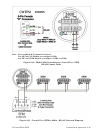
Figure 2-24 - 3-Wire RTD Temperature Input Wiring
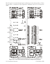
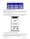
To install the RTD Probe, screw the Fitting Body into the thermowell with a 7/8”open-end
wrench. While applying pressure against the sheath to force the Tip of the RTD Probe into
the bottom of the thermowell (so that the Probe Tip is in contact with the thermowell),
tighten the Nut (9/16” open-end wrench) against the 7/8” Fitting Body (see Figure 2-25).