


CI-CW MICRO/CW EFM Appendix E - Display/Keypad / E-11
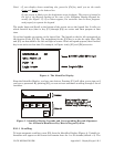
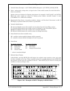
Notes for Figure 12
1. Variable Name (Example 1: @GV.FLOW_RATE) (Example 2: @GV.TOTAL_FLOW_RATE)
2. Value - analog value, string value, or logical value. Values which cannot fit in this field will be
shown as asterisks.
Analog values are displayed in floating point format, for example, 0.0125, 99.627, and 1287.66.
When the value cannot be shown in floating point format, scientific format is used
(1.287668E+10 or 1.25E-02 for example).
3. Questionable Data Status - for analog variables, column 1 will be clear if the status is valid. It
will display a question mark if the status is questionable.
4. Variable Inhibit Status
CE (Control Enable) means this variable can be updated by the ControlWave project.
CI (Control Inhibit) means the variable cannot be updated by the ControlWave project.
ME (Manual Enable) means the variable can be changed manually.
MI (Manual Inhibit) means the variable cannot be changed manually.
5. Alarm Enable (for alarm variables only)
AE - variable is alarm enabled (changes will be reported).
AI - variable is alarm inhibited (changes will not be reported).
6. Alarm State
For Analog Variables
: For Logical Variables:
HH - high-high alarm TA - true alarm
HI - high alarm FA - false alarm
LO - low alarm CA - change-of-state alarm
LL - low-low alarm
! - alarm is unacknowledged
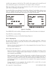
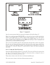
7 Multiple Signal Display
In Read Mode, pressing MULT (F3) will display the variable name extension, value, and units
for three variables at one time. These variables include the variable displayed when NEXT (F2)
was pressed and the next two variables in the list. Press SNGL [F3] to return to viewing one
variable at a time (see Figure 12A).
Figure 12A - Example of MULT Display in READ Mode