


C-16 / Appendix C - Hardware Installation Guide CI-ControlWave EFM
• The wire ends should be tinned with solder prior to insertion into the Chassis
Ground Lug. Note: Use a high wattage Soldering Iron.
• The ground wire should be run such that any routing bend in the cable has a
minimum radius of 12-inches below ground and 8-inches above ground
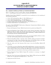
Step 1. Hardware Configuration (Continued)
7. Install the Bezel/Bezels so that the I/O Modules are covered.
8. Install RTD (wiring and Probe) (see Section 2.3.5 of this manual).
9. Install the Rechargeable Lead Acid Battery and Solar Panel (if provided) (see Sections
2.3.9.3 and 2.3.9.4.
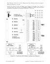
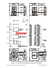
10. Connect DC Power wiring to the ControlWave EFM’s SCM Module (see Section 2.3.9,
2.3.9.1 and 2.3.9.2 and Figure C-2).
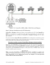
SCM Connector TB1 provides 3 input connections for bulk power as follows:
TB1-1 = (+VIN) (+4.5/4.9V to +16.0V dc for +6V) (+9.6/10.3V to +16.0V dc for +12V)
TB1-2 = (-VIN) (Supply Ground)
TB1-3 = Chassis Ground - CHASSIS (;)
11. Apply power to the ControlWave EFM. Continue with Steps 2 through 6 below and
Section 2.4.1, and the ControlWave EFM will be ready for on line operation.
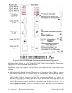
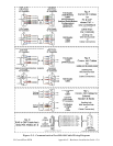
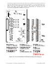
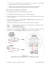
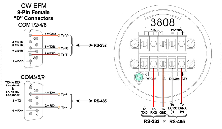
Figure C-11
Model 3808 Transmitter to ControlWave EFM Comm. Cables