


G-4 / Radio Ready Installation Guide CI-ControlWave EFM
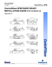
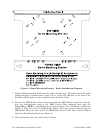
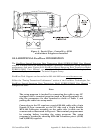
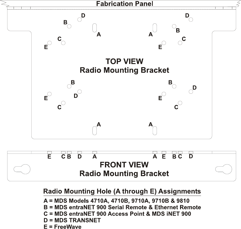
Figure 2 - Radio Mounting Bracket - Radio Installation Diagram
7. Plug the Radio Interface Cable into the radio’s Comm. Port. The other end of this cable
should already be installed into Comm. Port 2. of the CPU Module. In the case of the
FreeWave Radio, power is also supplied via the Interface Cable.
8. Remove the MDS Radio’s Power Connector from the MDS Radio in question and con-
nect the unterminated ends of the MDS Power Cable (shipped loose with the
ControlWave EFM) to the MDS Power Connector (Red = Pos. and Black = GND) (see
Figure 1). Plug the end of the MDS Radio Power Cable that you just dressed into the
MDS Radio. Plug the other end of the MDS Radio Power Cable into connector TB3 of
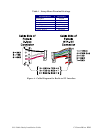
the Power Distribution Board (see Figure 4).
9. After testing the unit, close and secure the Door.