


2-10 / Installation & Operation CI-ControlWave EFM
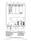
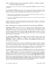
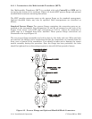
2.3.1.1 Connection to the Multivariable Transducer (MVT)
One Multivariable Transducer (MVT) is provided with each ControlWave EFM and is
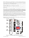
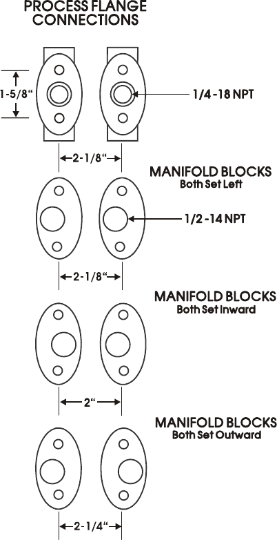
secured to the bottom of the enclosure. Figure 2-5 details MVT process flange and optional
manifold block connector mounting dimensions.
The MVT provides connection ports on the process flange as the standard arrangement.
Optional manifold blocks may also be specified. Both arrangements are described as
follows:
Standard Process Flange: Two process flanges containing the connection ports are as-
sembled to the transmitter. Port designations (L and H) are stamped on the body of the
flanges. Ports accept 1/4-18 NPT pipe connections on 2-1/8 in. centers for connection to
orifice taps or a standard three-valve manifold. These process flange connections are
illustrated at the top of Figure 2-5.
The two process flange assemblies are held in place by four bolts and nuts. When the bolts
are removed, the flanges can be repositioned so that the connections can emanate from the
front, rear or bottom of the transmitter. Care should be taken not to damage the sensor
module assembly during this procedure. Once the flange has been positioned, the bolts
should be tightened in an alternating sequence to about 20-30 foot-pounds of torque.
Figure 2-5 - Process Flange and Optional Manifold Block Connectors