


C-6 / Appendix C - Hardware Installation Guide CI-ControlWave EFM
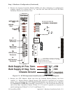
Expansion Communications Module:
COM4, COM5, COM6 & COM7 on 1
st
ECOM Bd., - assigned to Base Housing Slot #3
COM8, COM9, COM10 and COM11 on 2
nd
ECOM Bd., assigned to Base Housing Slot #4
COM4/8 - Port 1: ECOM Bd. J1, PC/AT 9-Pin Male D-Sub - Both RS-232
COM5/9 - Port 2: ECOM Bd. J2, PC/AT 9-Pin Male D-Sub - Both RS-485
COM6/10 - Port 3: ECOM Bd. Piggy-back Radio Module (FreeWave or MDS TransNet
Spread Spectrum Modem) Antenna connector provided (Optional)
COM7/11 - Port 4: ECOM Bd. Piggy-back Modem Module (Multitech 56KB PL/PSTN
Modem) RJ-11 connector provided (Optional)
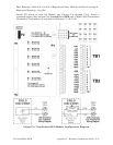
Communication Ports COM1, COM2, COM3, COM4, COM5, COM8 and COM9 support
serial asynchronous operation. Communication Ports COM1, COM2, COM4 and COM5
support RS-232 while COM3, COM5 and COM9 support RS-485 operation. Com-
munication Ports COM4/8, COM5/9, COM6/10 and COM7/11 reside on optional
Expansion Communications Modules (ECOM1/2). ECOM1 must reside in Base Chassis
Backplane Slot #3 while ECOM2 must reside in Base Chassis Backplane Slot #4. ECOM
Modules have one RS-232 Port and one RS-485 Port. Additionally, an ECOM Module
may optionally contain a 56Kbaud PSTN Modem and/or a Spread Spectrum Modem
(Radio). Any communication port can be configured for local communications, i.e.,
connected to a PC loaded with ControlWave Designer and OpenBSI software.
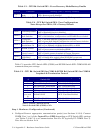
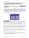
The pin
labels for the 9-pin, RS-232/485 interface are provided in Table C-4.
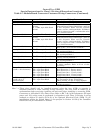
Table C-4 - RS-232 Ports COM1/2/4/8 and RS-485 Ports COM3/5/9
Connector Pin Assignments
Pin
#
Signal
RS-232
Description:
RS-232 Signals
Signal
RS-485
Description:
RS-485 Signals
1 DCD Data Carrier Detect Input N/A
2 RXD Receive Data Input RXD- Receive Data - Input
3 TXD Transmit Data Output TXD- Transmit Data - Output
4 DTR Data Terminal Ready Output TXD+ Transmit Data + Output
5 GND Signal/Power Ground GND/ISOGND* Ground/Isolated Ground*
6 DSR Data Set Ready Input RXD+ Receive Data + Input
7 RTS Request To Send Output N/A
8 CTS Clear To Send Input N/A
9 N/A N/A
* ISOGND on Isolated RS-485 Ports Only!
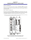
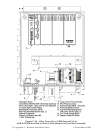
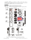
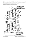
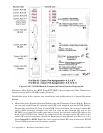
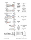
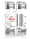
Remove any Expansion Communication Module and configure its Jumpers as required
(see Figures C-4A & C-4B). Install each Expansion Comm. Modules into the appropriate
ControlWave EFM Base Housing Communication I/O Slot. Expansion Comm. Modules
may reside in ControlWave EFM Base Housing Slots #3 and #4 ONLY (1
st
ECOM
resides in Slot #3, 2
nd
ECOM resides in Slot #4). Expansion Comm. Modules may not
reside in Expansion Housings.
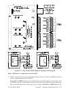
Spread Spectrum Modem Port
An optional Spread Spectrum Modem (Radio) is available on each Expansion Com-
munications Module (mounted piggy-back) and is assigned port status as follows: COM6 for
ECOM1 and COM10 for ECOM2. There are two unique radios offered. These radios will
only communicate with their own brand of radio, i.e., FreeWave radios are not compatible
with MDS radios. DTE/DCE serial data can be clocked into (transmit) or out of (receive) the
radio at a rate up to 115.2kHz.