


CI-ControlWave EFM Introduction / 1-27
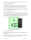
slave transmit and receive data on opposite lines; all slaves (from the first to the "nth") are
paralleled (daisy chained) across the same lines. The master node should be wired to one
end of the RS-485 cable run. A 24-gauge paired conductor cable, such as Belden 9843
should be used. Note: Only half-duplex RS-485 networks are supported.
From the factory COM1 defaults to 115.2 kbd using the BSAP Protocol. The remaining
serial communication ports, i.e., COM2 through COM5 default as follows:
COM2 – BSAP Slave @ 9600 Baud
COM3 – BSAP Master @ 9600 Baud (for use with Bristol Babcock 3808 MVT Transmitters)
*COM4 – MODBUS Master @ 9600 Baud (for use with Daniel 2251 Chromatograph)
*COM5 – MODBUS Master @ 9600 Baud (for use with Rosemount Transmitters)
* COM4 and COM5 are situated on an optional Expansion Comm. Module.
1.5.5.1 BSAP Message Support
The ControlWave EFM supports the same subset of BSAP messages as the other
ControlWave products.
1.5.6 Discrete and Analog I/O EFM Functionality
ControlWave EFM electronic flow meters may be equipped with a variety of I/O Modules
(see Sections 1.3.6 through 1.3.6.4). While using the standard application program, inputs
and outputs required for measurement and control are mapped to the application using the
configuration Web pages. Analog Alarm limits for variables required by the standard
application program are defined via the configuration Web pages. Discrete Input alarms
associated with the standard application program can be enabled or disabled on a per point
basis via the configuration Web pages. Control algorithms (flow control, sampler control,
odorant control, etc.) are selected via the configuration Web pages.
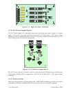
1.5.6.1 Flow Rate Control - DDC (jog control) using PID
When the user configures the ControlWave EFM to perform flow rate control, the two
digital output signals are wired to the Open and Close inputs of a controller. The
ControlWave EFM uses a Proportional/Integral/Derivative (PID) algorithm to cause the
measured rate of flow to match a user-entered setpoint. When the flow rate is below the
setpoint, the Open output is pulsed. When the flow rate is above the setpoint, the Close
output is pulsed. The PID equation calculates the duration of the Open or Close pulse. The
minimum pulse duration is 1.0 seconds. The user changeable parameters are:
• Flow Setpoint in MSCFH
• Deadband in % of setpoint
• Proportional Gain
• Integral Time in repeats/minute
• Derivative Time in seconds
• Valve Travel Time (full close to full open)
• Process Control Limiting
• Pressure Override Limits
The flow control algorithm runs once per second.