


1-8 / Introduction CI-ControlWave EFM
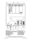
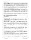
1.3.1 Enclosure
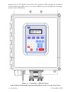
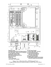
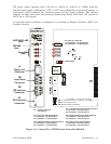
ControlWave EFMs are housed in a standard Hoffman® Enclosure. External dimensions
(excluding added hardware and Cover Latches) are approximately 14.56” high, by 12.97”
wide, by 8.31” deep. When present, the Multivariable Transducer adds 2.89” to the height of
the unit. The enclosure consists of two pieces, the body and the Instrument Front Cover. A
continuous gasket seals the unit when the Instrument Front Cover is closed. A hinge on the
left side (facing the front of the unit) is formed by molded channels on the Instrument Front
Cover and the body that capture a stainless steel pin. Two latches on the enclosure’s right
side secure the Instrument Front Cover when it is closed.
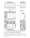
A weatherproof communication connector, either a 9-Pin male D-Type connector or a a
circular 3-pin connector, (the Local Port) is mounted to the bottom of the enclosure and
connected internally to RS-232 Comm. Port 1 provides connection for a local
communications device, typically a PC. Communications rate is configurable 300 to 115.2
KB (115.2 KB - default).
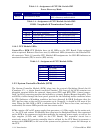
Enclosures are provided with either a 2-button 4 X 20 LCD display or a 4 X 20 LCD display
supported by a 25-button keypad. In normal operation, the display stays off after the unit
has been configured and placed into service. The operator may activate the display at any
time by pressing the appropriate front panel button.
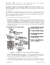
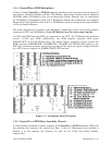
1.3.2 CPU Module
The CPU Module houses the CPU Board. This multilayer board provides ControlWave
MICRO EFM CPU, I/O monitor/control, memory and communication functions. Control-
Wave MICRO EFM CPU Modules operate over an extended temperature range with long-
term product reliability.
ControlWave EFM CPU Boards are based on Sharp’s LH7A400 System-on-Chip ARM
microprocessor with 32-bit ARM9TDMI RISC Core. The CPU operates at 1.8V with a
system clock speed of 33 MHz. The Microcontroller is packaged in a 256-pin Plastic Ball
Grid Array. In addition to the microprocessor and control logic, the CPU Board includes two
RS-232 and one RS-485 communication ports, 2MB of battery backed Static RAM (SRAM),
512kB Boot/Downloader FLASH, 8MB simultaneous read/write FLASH and an I/O Bus
Connector.
CPU Modules are provided backup power via a piggyback mounted Battery Backup board
equipped with a coin cell socket that accepts a 3.0V, 300mA-hr lithium battery. This 3.0V
battery provides backup power for the real-time clock and the system’s Static RAM (SRAM).
Backup power is enabled when JP1 on the Battery Backup Bd. is installed.
If the 3.3Vdc that powers the unit goes out of specification, a supervisory circuit on the
Battery Backup Board switches the battery voltage to the VBAT3.3 hardware signal (used
by the CPU’s SRAM and RTC). This supervisory circuit also generates a BATTERYGOOD
signal when the battery voltage is above 2.2V.
The system SRAM is specified to have a standby current of 20:A maximum for each part
(plus 2uA for the RTC). For a system containing 2MB of System SRAM, a worst-case
current draw of 42:A allows a battery life of approximately 7142 hours.
A supervisory circuit is used to switch to battery power when VCC falls out of specification.
For maximum shelf life, the battery may be isolated from the circuit by removing the