


3-6 / Service CI-ControlWave EFM
+16Vdc), you can determine the point at which the unit turns off, i.e., the point at which the
PWRGOOD LED on the SCM goes OFF (Vt-). If the value of the bulk power supply’s +6Vdc
or +12Vdc output approaches the value of Vt+ or Vt- it should be replaced by a power
supply with the correct +6V or +12V output.
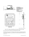
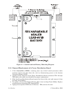
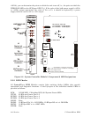
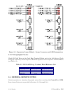
JP5, JP6, JP7, JP8 & JP9
1-to-2 Installed = 12V Bulk System
2-to-3 Installed = 6V Bulk System
P1
1
1
2
JP9
JP8
JP6
JP5
JP7
1
1
1
CR27
CR26
CR25
CR24
(Red)
I DLE LED
(Red)
Sta us LEDs
TB1
Input Power
Connector
(Red)
WATC HDO G LED
TB2
RTD Inte rfa c e
Connector
P2
MVT Interface
Connector
J2
Display Intf.
Connector
1A
J2
RJ- 45
TB1- 1
TB1- 2
TB1- 3
(+4.5/4.9Vdc to +16.0Vdc for +6V supply)
+VIN (+9.6/10.3Vdc to +16.0Vdc for +12V supply)
-VIN (Supply Ground)
Chassis Ground (CHASSIS)
SW1 = Mode Switch
Figure 3-2 - System Controller Module’s Component & LED Designations
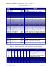
3.3.2 LED Checks
All ControlWave EFM Modules contain light emitting diodes (LEDs) that provide
operational and diagnostic functions. A brief synopsis of the individual module LEDs is
provided as follows:
SCM: 1 IDLE LED, 1 Watchdog LED, & 6 System Status LEDs
CPUM: 2 LEDs per Comm. Port = 6
ECOM1: 2 LEDs per Comm. Port = 8
ECOM2: 2 LEDs per Comm. Port = 8
AI/OM: None
DI/OM: 1 LED per DI x 12 = 12 DI LEDs, 1 LED per DO x 4 = 4 DO LEDs
HSCM: 1 LED per HSC x 4 = 4 HSC LEDs
MI/OM: None