


CI-CW MICRO/CW EFM Appendix D - Radio/Modem Installation Guide / D-9
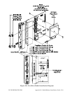
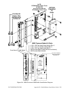
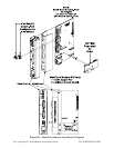
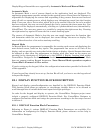
6. Snap the Cover Panel onto the Expansion Comm. Module PCB and insert the ECOM
Module into the appropriate Backplane Slot, i.e., Slot 3 or 4.
7. Apply power and test the unit.
D2.1.2 Configuring the MultiTech Modem (MT5634SMI)
To configure a Model MT5634SMI Modem (installed on an Expansion Communication
Module), perform the following nine (9) steps:
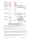
1. If required, remove the Exp. Comm. Module from the unit in question (see Figure D1).
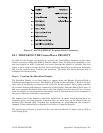
2. Place the modem into configuration mode by setting Expansion Comm. Module Jumper
JP2 onto pins 2 and 3. This will enable configuration of the modem through Comm. Port
4 for modem on ECOM1 or through COMM. Port 8 for modem on ECOM2.
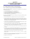
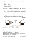
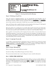
3. Connect a Full Duplex ControlWave Null Modem Cable (see Figure D3) between a PC
and Comm. Port 4 (ECOM1) to configure modem on ECOM1 or Comm. Port 8 (ECOM2)
to configure modem on ECOM2.
4. Open Hyperterminal on the PC and set the PC communication port settings as follows:
Bits per second: 9600
Data bits: 8
Parity: None
Stop bit: 1
Flow Control: None
5. Send Factory Default = AT&F0.
6. Disable Flow Control = AT&K0.
7. Set baud rate using AT Command: AT$SB9600, or whatever baud rate you require.
8. Write to memory = AT&W.
9. Set Expansion Comm. Module Configuration Jumper JP2 into a storage position, i.e.,
parked (no connection).