


2-14 / Installation & Operation CI-ControlWave EFM
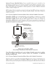
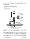
For safety reasons and to prevent accidental damage to a user supplied external bulk DC
Power Supply, it is recommended that pluggable Terminal Block connector TB1 be discon-
nected from the SCM until the entire unit has been wired, and hardware configured.
Sections 2.3.9.1 & 2.3.9.2 provide details on DC Power Connector TB1 wiring.
Table 2-1 - System Controller Module Switch SW1 – User Configurations
Switch Function Setting - (ON = Factory Default)
SW1-1/2
Recovery/Local
Mode
Both Open/Closed = Recovery Mode
SW1-1 Open (right) & SW1-2 Closed (left) = Local Mode
Note: Only SCM Switch SW1 settings listed in this table have been tested.
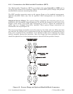
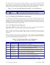
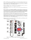
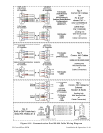
2.3.3 CPU Module & ECOM Module Configuration
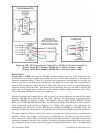
To configure the CPU Module, Jumpers must be set (see Figure 2-9), DIP-Switches must be
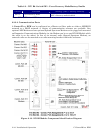
set (see Section 2.3.3.1) and Communication Ports must be wired (see Sections 2.3.3.2
through 2.3.3.3). The CPU Module resides in Base Chassis Backplane Slot #2 (see Figure 2-
2). Backplane Slot #2 provides 44-pin female interface connector P2 on the bottom and 36-
pin female interface connector P3 on the top.
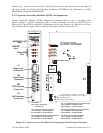
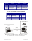
2.3.3.1 CPU Module Switch Configuration
ControlWave EFM CPU Module DIP-Switches must be set for the desired performance
options. Tables 2-2, 2-3 and 2-6 provide an overview of switch settings.
SW2-1 set OFF will disable the system from entering a watchdog state when a crash or
system hangup occurs. Setting SW2-1 OFF prevents the system from automatically
restarting.
SW2-2 set OFF prevents changing the Soft Switches, other configurations and FLASH files,
i.e., these items are locked. To change Soft Switch, configuration and FLASH files SW2-2
must be set to the ON position (see Section 2.4.4).
Table 2-2 - CPU Bd. Switch SW2 - User Configurations
Note: Except for SW2-4, ON = Factory Default
Switch Function Setting - (ON = Factory Default)
SW2-1 Watchdog Enable
ON = Watchdog circuit is enabled
OFF = Watchdog circuit is disabled
SW2-2
Lock/Unlock
Soft Switches
ON = Write to Soft Switches and FLASH files
OFF = Soft Switches, configurations and FLASH files are locked
SW2-3
Use/Ignore
Soft Switches
ON = Use Soft Switches (configured in FLASH)
OFF = Ignore Soft Switch Configuration and use factory defaults
SW2-4
Core Updump
See Section 3.6
ON = Core Updump Disabled
OFF = Core Updump Enabled via Mode Switch (SW1) on SCM
SW2-5 SRAM Control
ON = Retain values in SRAM during restarts
OFF = Force system to reinitialize SRAM
SW2-6
System Firmware
Load Control *
ON = Enable remote download of System Firmware
OFF = Disable remote download of System Firmware
SW2-7 N/A
SW2-8 Enable WINDIAG
ON = Normal Operation (don’t allow WINDIAG to run test)
OFF = Disable boot project (allow WINDIAG to run test)
* = Boot PROM version 4.7 or higher and System PROM version 4.7 or higher