


CI-ControlWave EFM Appendix C - Hardware Installation Guide / C-21
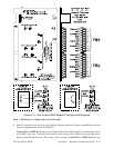
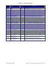
Table C-6 - LED Assignments
Module
LED
Name
LED
Color
Function
SCM * IDLE Red ON = Idle
SCM * WD Red ON = Watchdog Condition - OFF = Normal
SCM 6 STATUS Red See Figure C-13
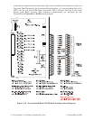
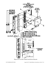
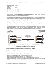
CPUM C1 RX (Comm 1) Red ON = RX Activity (Top-Left - see Fig C-3)
CPUM C1 TX (Comm 1) Red ON = TX Activity (Top-Right -see Fig C-3)
CPUM C2 RX (Comm 2) Red ON = RX Activity (Middle-Left - see Fig C-3)
CPUM C2 TX (Comm 2) Red ON = TX Activity (Middle-Right -see Fig C-3)
CPUM C3 RX (Comm 3) Red ON = RX Activity (Bottom-Left - see Fig C-3)
CPUM C3 TX (Comm 3) Red ON = TX Activity (Bottom-Right -see Fig C-3)
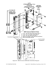
ECOM1 C1 RX (Comm 4) Red ON = RX Activity (Top-Left - see Fig C-4)
ECOM1 C1 TX (Comm 4) Red ON = TX Activity (Top-Right -see Fig C-4)
ECOM1 C2 RX (Comm 5) Red ON = RX Activity (2
nd
from Top-Left - see Fig C-4)
ECOM1 C2 TX (Comm 5) Red ON = TX Activity (2
nd
from Top-Right -see Fig C-4)
ECOM1 Radio RX (Comm 6) Red ON = RX Activity (3
rd
from Top-Left - see Fig C-4)
ECOM1 Radio TX (Comm 6) Red ON = TX Activity (3
rd
from Top-Right -see Fig C-4)
ECOM1 Modem RX (Comm 7) Red ON = RX Activity (Bottom-Left - see Fig C-4)
ECOM1 Modem TX (Comm 7) Red ON = TX Activity (Bottom-Right -see Fig C-4)
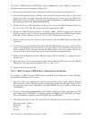
ECOM2 C1 RX (Comm 8) Red ON = RX Activity (Top-Left - see Fig C-4)
ECOM2 C1 TX (Comm 8) Red ON = TX Activity (Top-Right -see Fig C-4)
ECOM2 C2 RX (Comm 9) Red ON = RX Activity (2
nd
from Top-Left - see Fig C-4)
ECOM2 C2 TX (Comm 9) Red ON = TX Activity (2
nd
from Top-Right -see Fig C-4)
ECOM2 Radio RX (Comm 10) Red ON = RX Activity (3
rd
from Top-Left - see Fig C-4)
ECOM2 Radio TX (Comm 10) Red ON = TX Activity (3
rd
from Top-Right -see Fig C-4)
ECOM2 Modem RX (Comm 11) Red ON = RX Activity (Bottom-Left - see Fig C-4)
ECOM2 Modem TX (Comm 11) Red ON = TX Activity (Bottom-Right -see Fig C-4)
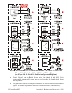
DI/OM
Input (12 LEDs)
(1 Per Point)
Red
LED ON = Input is present
LED OFF = Input is not present (see Fig C-6)
DI/OM
Output (4 LEDs)
(1 Per Point)
Red LED ON = Output is ON (see Fig C-6)
HSCM
INPUT (4 LEDs)
(1 Per Point)
Red
LED ON = Input activity on input is present
LED OFF = No activity on input (see Fig C-8)
* = see Figure C-2