


0 - 4 / Contents CI-ControlWave EFM
CI-ControlWave EFM
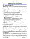
ControlWave EFM
Electronic Flow Meter
TABLE OF CONTENTS
SECTION TITLE PAGE #
Section 2 - INSTALLATION & OPERATION (Continued)
2.4.2.3 Remote Upgrade of ControlWave EFM Firmware ...................................................2-58
2.4.3 Operation of the Mode Switch......................................................................................2-59
2.4.4 Soft Switch Configuration and Communication Ports ...............................................2-59
2.4.5 Optional Display/Keypad Assemblies..........................................................................2-60
2.4.5.1 Operation of the Dual-button Display/Keypad Assembly ..........................................2-62
Section 3 - SERVICE
3.1 SERVICE INTRODUCTION ........................................................................................3-1
3.2 COMPONENT REMOVAL/REPLACEMENT PROCEDURES...................................3-1
3.2.1 Accessing Modules For Testing......................................................................................3-1
3.2.2 Removal/Replacement of the Bezel Assembly...............................................................3-2
3.2.3 Removal/Replacement of the CPU Module ...................................................................3-2
3.2.4 Removal/Replacement of the System Controller Module.............................................3-2
3.2.5 Removal/Replacement of an I/O Module .......................................................................3-2
3.2.6 Removal/Replacement of an Expansion Comm. Module ..............................................3-3
3.2.7 Removal/Replacement of a Rechargeable Lead-acid Battery.......................................3-3
3.2.8 Removal/Replacement of a Power Distribution Board .................................................3-4
3.2.9 Removal/Replacement of a 21V Power Supply Board ..................................................3-5
3.2.10 Removal/Replacement of a Digital to Relay I/O Board.................................................3-5
3.2.11 Removal/Replacement of an External Radio/Modem ...................................................3-5
3.3 TROUBLESHOOTING TIPS.........................................................................................3-5
3.3.1 System Controller Module (SCM) Voltage Checks.......................................................3-5
3.3.2 LED Checks ....................................................................................................................3-6
3.3.3 Wiring/Signal Checks...................................................................................................3-10
3.4 GENERAL SERVICE NOTES.....................................................................................3-10
3.4.1 Extent of Field Repairs.................................................................................................3-11
3.4.2 Disconnecting RAM Battery ........................................................................................3-11
3.4.3 Maintaining Backup Files............................................................................................3-11
3.5 WINDIAG DIAGNOSTICS ..........................................................................................3-11
3.5.1 Diagnostics Using WINDIAG ......................................................................................3-14
3.5.1.1 Communications Diagnostic Port Loop-back Test......................................................3-14
3.5.1.2 Serial Comm. Port Eternal Loop-back Test Procedure ..............................................3-14
3.6 CORE UPDUMP...........................................................................................................3-16
3.7 CALIBRATION CHECKS............................................................................................3-16
Section 4 - SPECIFICATIONS
4.1 CPU, MEMORY & PROGRAM INTERFACE ..............................................................4-1
4.2 COMMUNICATION PORTS .........................................................................................4-1
4.3 SYSTEM CONTROLLER MODULE ............................................................................4-2
4.3.1 Input Power Specs..........................................................................................................4-2
4.3.2 Power Supply Sequencer Specs. ....................................................................................4-3