


CI-ControlWave EFM Appendix F / F-25
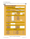
F.6.2.2 Frequency Input
The frequency input must be brought into one of the two high-speed counter (HSC) inputs
on the I/O board. Users select the two I/O points to which the typical turbine, PD, or
ultrasonic meter is connected. However; if using an Invensys Auto-Adjust Turbo-Meter,
both HSC inputs are used to select the Auto-Adjust Algorithm. To select the Auto-Adjust
Algorithm, the user will toggle the push button under Source
fromr High Speed Counter to
Auto Adjust Module
. In this case, the user selects which point will be used for the Main
Rotor and which point will be used for the Sense Rotor.
Further configuration of the Auto-Adjust Turbine Meter is performed via the Auto-Adjust
Configuration Page. (For a description of the items on the Auto-Adjust Configuration Page,
see the ACCOL3 Function Block Help Documentation).
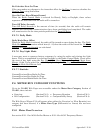
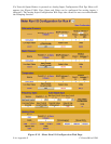
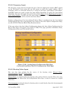
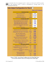
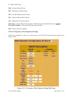
If the user selects the Auto-Adjust Configuration button the Auto-Adjust Configuration for
Run # Web Page will appear (see Figure F-16B). This page provides Calibration Data,
Configuration Data and Calculated Factors.
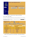
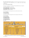
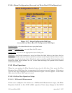
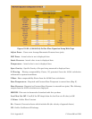
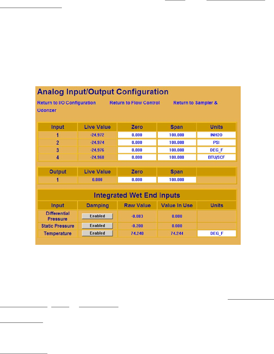
Figure F-16A - Analog Input Configuration Web Page
(Accessed from Meter Run I/O Configuration Web Page)
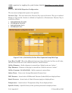
F.6.2.3 Heating Value Input
The user has four options for the source of the heating value, Manual Entry
,
Chromatograph
, AGA5 or Analog Input.
Manual Entry
is selected when the heating value will be directly entered. This value may
be entered via the Meter Run I/O Configuration Web Page, or may be written to a signal
externally.
Chromatograph
is selected when the heating value is read directly from the chromatograph
via the MODBUS interface.