


2-28 / Installation & Operation CI-ControlWave EFM
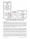
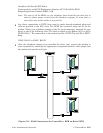
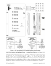
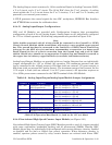
removable Terminal Block connectors and field devices (see Figure 2-18). Use AWG
14 or smaller wire, (consult with the field device manufacturer for recom-
mendations). Leave some slack and plan for wire routing, identification, main-
tenance, etc. The bundled wires are to be routed in/out through the bottom of the I/O
Module Assembly between the Terminal Block Assembly and the Terminal Housing
Assembly. All I/O wiring should be routed in/out of the enclosure through 1” NPT
Conduit Hub.
Non-Isolated I/O Module wiring information is provided in the following sections:
Section 2.3.4.4 = Digital I/O Module (12 DI & 4 DO)
Section 2.3.4.5 = Analog I/O Module (6 AI & 2 AO) and Analog Input Module (6 AI)
Section 2.3.4.6 = High Speed Counter Module (4 HSC)
Section 2.3.4.7 = Mixed I/O Module (6 DI/DO, 4AI, 2 HSC & 1 optional AO
Note: The ControlWave Loop Power Supply can be used to provide
regulated and isolated 24Vdc field power for externally powered
non-isolated I/O see PIP-ControlWaveLS).
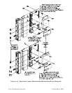
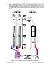
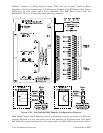
3. Align the I/O Module with the assigned I/O Slot and install the unit into the
Chassis. Make sure that the I/O Module Cover snaps into the applicable notches in
the Chassis Assembly.
4. Plug the Local Cable Assemblies onto the appropriate I/O Module connectors.
5. When two I/O Modules have been installed into the Chassis (with field wiring), a
Bezel Assembly should be installed to cover, protect and dress the unit.
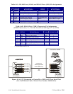
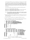
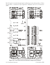
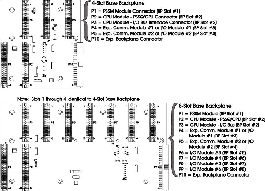
Figure 2-17 - ControlWave EFM Slot Assignments