


F-2 / Appendix F CI-ControlWave EFM
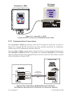
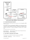
PC/Laptop
Computer
Control
EFM
Wave
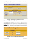
Figure F-1 - ControlWave EFM
Connected to PC via the Local Communications Cable
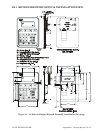
F.2.1 Communication Connections
The ControlWave EFM communicates with the PC through the Local Port as shown in
Figures F-1 through 2B. The Local Port has been provided specifically for installation,
startup and on-site configuration and data collection.
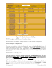
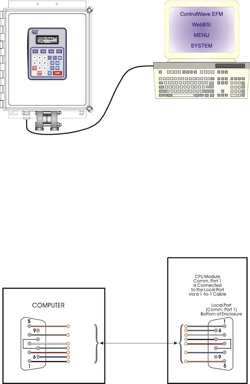
For ControlWave EFM’s equipped with a D-type Local Port, local communications between
the ControlWave EFM and the PC is provided over a standard ControlWave null-modem
cable (see Figure F-2A). Units equipped with the circular 3-pin Local Port utilize a special
cable as illustrated in Figure F-2B.
Control EFM
Wave
9-Pin Female
“D” Connector
(Looking into
Wire Terminal Side
of
Cable Connectors)
3 = TXD
6 = DSR
7 = RTS
8 = CTS
4 = DTR
2 = RXD
1 = DCD
5 = GND
To P2 Pin-4
To P2 Pin-2
To P2 Pin-7
To P2 Pin-3
To P2 Pin-6
To P2 Pin-5
To P2 Pin-1
9-Pin Female
“D” Connector
3 = TXD
6 = DSR
7 = RTS
8 = CTS
4 = DTR
2 = RXD
1 = DCD
5 = GND
or
vice
versa
Figure F-2A - ControlWave EFM (with D-type Local Port)
Null Modem Cable (Bristol P/N 392843-01-3) Connection Diagram