


75
This section covers replacement of many
components of the drive. Note that some
components are not field-repairable. Refer to
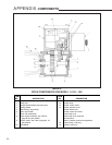
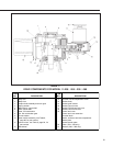
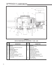
the drive outline dimension drawings on pages
8–14 and to the cutaway illustration on page 4 for
location of components on the drive.
If it should ever be necessary to replace the
output gear, shaft, or output shaft bearings, a
major overhaul is required and the drive should be
returned to the factory. During a major overhaul,
the factory repair department will update the drive
to include all possible engineering improvements.
See "HOW TO OBTAIN SERVICE" on page 87.
GASKETS
During routine service, inspect the cover,
motor, and change gear plate gaskets for wear or
damage. In order to protect internal components,
worn or damaged gaskets and O-rings should be
replaced.
To remove, scrape all of the old adhesive and
gasket material from the body housing and cover.
Cement the new gasket to the drive body using
a gasket cement such as 3M #847 Rubber and
Gasket Adhesive, or equivalent.
SEALS
Worn or damaged output shaft, control end
shaft, and motor shaft seals should be replaced
to prevent damage to internal bearings and drive
train parts.
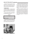
To remove the shaft seal, push the blade of a
small screwdriver along the shaft and under the
seal lip. CAUTION: The seal is approximately
1/4" (6 mm) wide. Do not force the screwdriver
blade beyond the width of the seal; damage to
the shaft bearing could result. Pry up on the seal
and force it out of the housing. Clean the shaft
and housing then press in the replacement seal
with the closed side facing outward.
BEARINGS
The Beck control drive contains ball bearings
on the output shaft, control end shaft, and motor
shaft. Bushings and thrust washers are used on
combination gears. Field replacement of these
components is not recommended.
Motor shaft bushings in the body of the
11-159/-169 and 11-409/-469 can be replaced.
TIP: To remove, fill the bushing with a heavy
grease. Select a drive pin that slip fits into the
bushing. Insert the pin into the bushing and tap
with a mallet. This will force the bushing out of
the body casting.
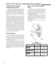
MOTOR
The control motor is not field-repairable.
Disassembly of the motor will result in a loss of
torque that can only be restored by returning the
motor to the factory for re-magnetizing.
CAUTION
If your drive has a linkage, before removing
the control motor, block the control drive crank
arm to prevent the crank arm and the gear train
from moving when the motor is removed.
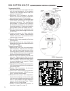
To remove the motor, first disconnect the
motor wires in the terminal compartment of the
control drive.
In the 11-159/-169 drives, the Handswitch must
first be removed from the body before removing
the terminal block and plate as an assembly.
Follow the instructions in the paragraphs below.
In the 11-209/-269, -309/-369, and -409/-469
drives, remove the terminal block and plate as
an assembly. Remove the black wire from the
terminal post, cut the red motor wire near the
red-yellow-red butt joint and disconnect the
green wire from the motor capacitor. Remove
the mounting bolts and motor. Carefully slide the
motor out of the drive body.
To install the motor, insert the three-wire sleeve
through the wire hole in the motor mount and into
the terminal compartment. Carefully slide the
motor into the drive body. Rotate the motor shaft,
if necessary, to engage the pinion with the first
combination gear. Install motor mounting bolts
and torque to recommended values. See pages
8–14 for torque values. Reconnect the motor
wires. See the following section for reinstalling the
terminal plate.
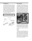
Motor Resistor and Capacitor
The motor resistor and capacitor are located
under the terminals in the terminal compartment. To
replace a resistor or capacitor, remove the terminal
cover.
In the 11-159/-169 drives, the Handswitch must
first be removed from the body before removing the
terminal block and plate as an assembly. Follow the
instructions in the following paragraph.
In the 11-209/-269, -309/-369, and -409/-469,
remove the terminal plate. Remove the existing
part and transfer the wires one at a time to the
replacement part. Inspect the terminal plate gasket
and replace if necessary. To ensure a watertight
seal between the plate and gasket, coat the gasket
with a thin film of grease before replacing the
terminal plate. Torque the screws to 3 Ib-ft (4 N•m).
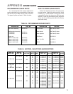
MAINTENANCE COMPONENT REPLACEMENT