


46
DCM-2 HART INTERFACE Configuration and Setup
0% and an over-travel limit switch is open. This
eliminates the nuisance message, but does not
eliminate the message for other scenarios like
the Handswitch being in the STOP position.
Changing Overtravel
Annunciation
STEP 1 - From the HART
®
communicator
“Online” menu, move to the “General Setup”
menu and select the “LimitSwitch” parameter.
This is accomplished by using the up and down
arrow keys to select the appropriate item in each
menu and then moving forward by pressing the
right arrow key. Follow the Menu Tree (Figure 1,
page 34) to navigate.
STEP 2 - With the “LimitSwitch” parameter
selected, again press the right arrow key to
display the modifiable entry box, select either
"Accept" to turn off the HART warning or "Alert" to
ensure the HART warning is transmitted.
STEP 3 - With the desired selection
highlighted, push the F4 function key (which is
defined as the ENTER key at the bottom of the
display). Pushing this key enters the value and
reverts the display back to the "General Setup"
main menu.
STEP 4 - At the bottom of the "General Setup"
menu, the F2 function key should now be defined
as the SEND key. Push this key to execute the
change.
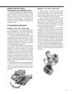
POSITION FEEDBACK SIGNAL
DCM-2 boards are equipped with a Feedback
Sourcing module that provides a 4–20 mA analog
output signal that represents the drive output
shaft position in terms of 0–100% of full directional
travel. This signal can be remotely monitored or
used by a controller or indicator. The user has
the option of enabling or disabling the signal.
Normally, the signal should be enabled , but in
a situation where the feedback is present, but
unused (i.e., not wired to a load) a HART
®
alarm
message will be present while communicating
using the 275/375 Communicator. This message
is helpful in alerting the user to open feedback
wiring, but it is a nuisance when the feedback
is purposely disconnected or unused. Disabling
the feedback signal turns off the output and
eliminates the message.
OVERTRAVEL ANNUNCIATION, CONT’D.
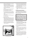
Enabling / Disabling Position
Feedback Signal
STEP 1 - From the HART
®
communicator
“Online” menu, move to the “Setup Checklist”
menu and select the “Feedback” parameter. This
is accomplished by using the up and down arrow
keys to select the appropriate item in each menu
and then moving forward by pressing the right
arrow key. Follow the Menu Tree (Figure 1, page
34) to navigate.
STEP 2 - With the “Feedback” parameter
selected, press the right arrow key to display the
two entry choices: “Enabled” or “Disabled”. Use
the up and down arrow keys to select the desired
parameter. “Enabled” enables the output signal,
while “Disabled” disables the output.
STEP 3 - With desired choice selected,
push the F4 function key which is defined as the
ENTER key at the bottom of the display. Pushing
this key enters the selected parameter and
reverts the display back to the “Setup Checklist”
main menu.
STEP 4 - At the bottom of the “Setup Checklist”
menu, the F2 function key should now be defined
as the SEND key. Push this key to execute the
change. This change should not effect drive
positioning but, as with all configuration changes,
carefully follow the on-screen warnings and
messages when proceeding.
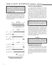
DEMAND SIGNAL
CHARACTERIZATION
The Beck DCM-2 is designed to receive a
4–20 mA (1–5 V dc) input Demand signal and
respond by repositioning the drive output shaft
in proportion to the signal. There are four ways
in which the DCM-2 can interpret the Demand
signal: Linear, Square Root, Dem Curve Special
and Square. The Linear interpretation, which is
most commonly employed, simply causes the
drive to position the output shaft in a one-to-one
relationship with the Demand. For example,
a 1% change in Demand always causes a 1%
position response. The Square Root relationship
produces a response proportional to the square
root of the Demand Signal. The Dem Curve
Special relationship allows a customized Demand
curve to be setup through a special submenu.
The Square relationship produces a non-linear
drive response proportional to the square of
the Demand signal. For example, a 25% input
Demand is interpreted as 0.25
2
or 0.0625
(6.25%). The square relationship helps to
linearize flow response of final control elements
that have quick opening characteristics.