


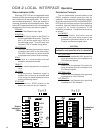
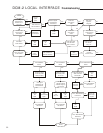
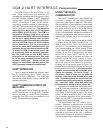

32
START
Is there a jumper
from terminal A
to terminal C?
Does drive work
with Handswitch?
Does drive
work properly
CW?
Does drive
work properly
CCW?
Does output shaft
move with Hand-
switch in “STOP”?
Does motor
appear to
energize?
Does drive run
randomly and/or
erratically?
Is the R/C
network correct?
Is there 0 volts
across fuse “F1”
of the DCM?
Is the DCM
"PWR" LED lit?
Is the “STAT” LED
on the DCM lit?
Is AC voltage at
terminals B & C
between 102 &
132 V ac?
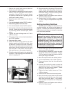
Replace the fuse,
see diagram on
p. 78 for location
Connect
proper
power
Install
jumper
Replace
the
DCM
Check
drive
calibration
Go back
to
start
Check for correct
R/C network,
see p. 79
Check SLM for
wear; rebuild or re-
place as necessary
Replace
faulty
components
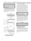
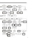
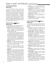
Is the “DEMAND”
LED lit?
Is the “POSITION”
LED lit?
Is the “TRQ/THRUST”
LED lit?
Check the voltage
across test points
TP2 & TP3 (R11)
Check the voltage
across test points
TP1&TP4
Is the torque sensing
cable connected
to the DCM?
Is the “TRQ/THRUST”
LED still on?
Is the “TRQ/THRUST”
LED still on?
Is the “TRQ/THRUST”
LED still on?
Is the signal out-
side the expected
calibration range by
>5% of span?
Is the signal
greater than the
LOS threshold?
Is the “DEMAND”
LED still on?
Is the “POSITION”
LED still on?
Connect
the
cable
Correct the
over-torque
condition
Remove
load from
crank arm
Replace
the
DCM
Replace
the
DCM
Apply
correct demand
signal
Recalibrate
drive,
see p. 24
Replace
the
DCM
Consult
Factory
YES
YES
YES
YES
YES
NO
NO
YES
YES
YES
YES
YES
YES
YES
YES YES
YES
YES YES
YES
YES
YES
YES
NO
NO
NO
YES
NO
NO
NO
NO
NO
NO
NO
NONO
NO
NO
NO
NO
NO
DCM-2 LOCAL INTERFACE Troubleshooting