


70
DCM-2 SERIAL INTERFACE Commands
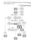
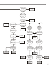
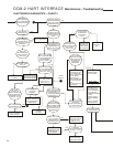
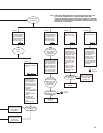
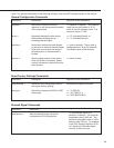
Note: For specific information on the following functions, see the HART interface section of the manual.
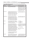
Command
dem100pctma n
trimdem4ma 4
trimdem20ma 20
demfunc n
demlos n
demlosgtp n
Description
Sets the Demand signal value that
corresponds to 100% drive position.
Calibrates the Demand signal at 4 mA. This
command should only be used when the
Demand signal at the drive is 4 mA. If the
Demand signal at the drive is greater or less
than 4 mA, an error will be returned. Note:
This parameter is factory configured and
normally does not require recalibration.
Calibrates the Demand signal at 20 mA.
This command should only be used when
the Demand signal at the drive is 20 mA. If
the Demand signal at the drive is greater or
less than 20 mA, an error will be returned.
Note: This parameter is factory configured
and normally does not require recalibration.
Sets and/or displays the Demand signal
input characterization function. The DCM-2
provides linear, square root, special curve or
square function characterization.
Sets and/or displays the Demand signal
threshold below which the DCM-2 recognizes
that the signal is lost. The threshold is
entered as a value in mA. This command
also sets and/or displays the action initiated
by the drive during LOS (Loss Of Signal).
LOS action options are "sip" (stay in place) or
"gtp" (go to position). Note that the command
always reports both settings, but only sets
one argument at a time. The command must
be used twice to set the threshold and action.
If the action is "gtp", then the command
demlosgtp (see below) must also be set.
The option "pat" is also available to prevent
error messages if the DCM-2 is not being
used with a Demand signal.
Sets and/or displays the position to which
the drive will run upon loss of the Demand
signal (LOS). This command has no effect if
the drive is set to "sip" (stay in place).
Argument n and Information
n = the Demand signal as a
decimal in milliamps. The minimum
acceptable value is the Demand at
0% plus 4.00 mA. For example, if the
0% Demand signal is 4.00 mA, then
the 100% Demand signal must be
8.00 mA or greater. The maximum
acceptable value is 21.00 mA.
A 4 mA Demand signal must be
present at drive terminals 14 & 15.
A 20 mA Demand signal must be
present at drive terminals 14 & 15.
n = "0" (linear)
n = "1" (square root)
n = "4" (special curve)
n = "5" (square).
n = the Demand signal in mA below
which LOS occurs. For example, in a
4–20 mA drive, if the desired LOS is
5% below the minimum signal, then
n = "3.20" mA.
— OR —
n = "sip", "gtp" or "pat".
Note: n values must be set
separately.
n = the desired position of the drive
expressed as a percentage of drive
travel (e.g., if the desired LOS
position is 50%, then n = "50.00").
Demand Signal Commands (con't)