


38
DCM-2 HART INTERFACE Communication
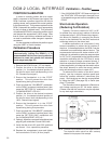
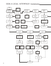
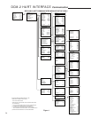
Configuration Menu
(Block 3C)
The Configuration menu serves as the
gateway to all of the drive operating setup
parameters. The user can select any of five
different setup submenus that can be used
to configure the drive based on the physical
layout and the desired operation. The five setup
submenus are described below. In addition
to these five setup menus, there is a "Restore
to Factory" selection which resets the drive
configuration to its as-shipped settings. There is
also a "User Default Setup" setting which resets
the drive configuration to the settings typical of
the applicable drive model type.
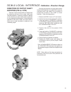
General Setup Submenu
(Block 4B)
This menu sets drive operating parameters.
The nine parameter entries are as follows:
1. Drive dir - Defines the rotation of the drive
output shaft, given an increasing Demand
signal, looking into the output shaft.
Options available are clockwise (CW) or
counterclockwise (CCW).
When the drive direction parameter is
changed, the DCM-2 automatically reverses
the analog position feedback signal such that
it is 4 mA at the 0% input signal position and
20 mA at the 100% position. No recalibration
of the CPS is required. This parameter is
normally set to CW on an increasing Demand
signal unless the user specified CCW prior to
shipment of the drive.
2. MaxTravel - The maximum available travel
distance of the output shaft in degrees.
This value is entered manually, and must
correspond to the actuator design.
3. Travel - The number of degrees of output
shaft travel for 100% span. Edit this value
to use a span shorter than the allowable
"MaxTravel".
4. StepSize - The typical change in Demand
signal that can occur before the output shaft
will reposition (expressed in percent of span).
5. Stall time - The DCM-2 provides stall
protection to the entire drive by shutting off
power to the motor and providing a HART
®
alarm. This entry configures the stall time
required to trigger the stall protection. At
the factory, stall time is normally set to 300
seconds, but can be edited and set for any
value between 30 and 300 seconds. This
value should be longer than the timing for full
drive travel.
6. StallProt - This entry is set as either “Enabled”
or “Disabled". It is used to remove motor
power if "Stall time" is reached.
7. LimitSwitch - This entry is set as either
"Accept" or "Alert" and is used to define
whether contacting a limit switch outside of
the normal travel range (0% to 100%) will
cause an error condition.
8. PositionUnit - Sets the numeric unit of
measure for the output shaft position in
degrees ("deg").
9. Temperature Unit - The unit of measure
for temperature. May be set for Fahrenheit
("degF") or Celsius ("degC").
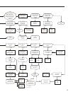
PositionSensrSetup Submenu
(Block 4C)
This menu is where all position sensor
and external position feedback signal setup is
performed. The eight parameter entries are as
follows:
1. Set Pos 0% - Selecting this parameter sets
the present position of the drive to the
minimum travel position. Equivalent to
pushing the SET POS 100% pushbutton.
2. Set Pos 100% - Selecting this item sets the
present position of the drive to the maximum
travel position. Equivalent to pushing the
SET POS 100% pushbutton.
3. PresCPS V - Displays the present value of
the internal Position Sensor voltage, which
may also be measured at TP4(+) and TP1(–)
on the DCM-2 board. May be edited in
the Calibration Trim menu for trimming the
Position Sensor A/D converter.
4. CPS Zero% - Displays the CPS voltage at
the zero percent output shaft position. May
be edited to define the CPS voltage at the
lowest operating point of travel.
5. CPS Span - Displays the CPS voltage span
for the maximum allowable output shaft
travel.
6. CPS RngLwr - Displays the CPS voltage at
the lowest available point of travel. Normally
set by the factory.
7. CPS RngUpr - Displays the CPS voltage
at the highest available point of travel.
Normally set by the factory.
8. Pos S/N - A number which uniquely identifies
the position sensor. May be edited.
9. Snsr Dir - Displays which direction of output
shaft movement will yield an increasing
internal Position Sensor signal. Normally set
at factory to "CW Incr" (signal increases as
the output shaft rotates CW).