


51
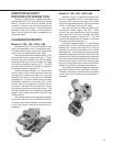
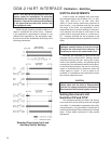
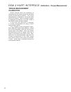
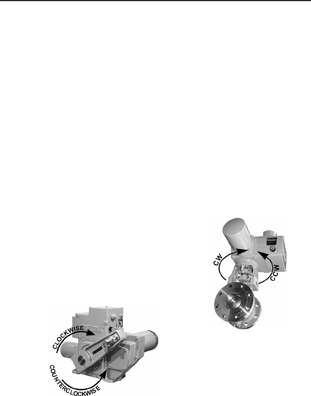
DIRECTION OF SHAFT
ROTATION (CW VERSUS CCW)
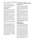
Direction of shaft rotation is determined when
looking at the end of the output shaft (see figures
below). Direction of rotation is defined as the
direction of output shaft rotation produced by
an increasing demand signal. Unless otherwise
specified at the time of order, the output shaft is
factory-set to rotate clockwise in response to an
increasing signal.
CALIBRATION PRIORITY
Models 11-159, -209, -309 & -409
Standard Group 11 drives are equipped with
fixed, non-adjustable, built-in mechanical stops.
All output shaft rotation must occur within these
stops, which are approximately 108° apart.
The over-travel limit switches are used to limit
the electrical control range of the drive. These
switches are cam operated and are set slightly
wider apart then the drive’s intended full range
of electronic operation (typically 100°). The limit
switches are positioned to provide an electrical
overtravel protection (typically 101°).
If the drive is short-stroked—i.e., the full travel
rotation from 0–100% is reduced to less than the
standard 100° rotation (see page 55)—it may be
desirable to reset the over-travel limit switches
(see page 52). If the limit switches are not reset,
Handswitch operation of the drive (CW, CCW)
will still result in the original full range of travel.
It is best to calibrate the drive and then set the
limit switches when short-stroking the drive. The
switches should be set just outside the calibrated
range to avoid tripping the switch at the 0% and
100% positions.
The auxiliary switches are also cam operated,
but have no affect on drive and DCM-2 operation.
Therefore, the auxiliary switches can be adjusted
at any time without affecting performance or
calibration.
Models 11-169, -269, -369 & -469
Standard Group 11 drives are equipped with
fixed, non-adjustable, built-in mechanical stops.
All output shaft rotation must occur within these
stops, which are approximately 108° apart; except
for the 11-169 stops, which are 98° apart.
The over-travel limit switches are used to limit
the electrical control range of the drive. These
switches are cam operated and are set slightly
wider apart then the drive’s intended full range
of electronic operation (typically 90°). The limit
switches are positioned to provide an electrical
overtravel protection (typically 91°).
If the drive is short-stroked—i.e., the full travel
rotation from 0–100% is reduced to less than the
standard 90° rotation (see page 55)—it may be
desirable to reset the over-travel limit switches
(see page 52). If the limit switches are not reset,
Handswitch operation of the drive (CW, CCW) will
still result in the original full range of travel. Because
the over-travel limit switches define the maximum
electrical drive range, if they are to be reset, they
should be adjusted before performing DCM-2
(demand and position) calibration procedures.
The auxiliary switches are also cam operated,
but have no affect on drive and DCM-2 operation.
Therefore, the auxiliary switches can be adjusted
at any time without affecting performance or
calibration.