


37
MENU DESCRIPTIONS
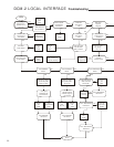
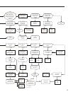
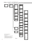
(See Figure 1, Page 34)
Online Menu
(Block 1)
When communications are established with
the communicator, the Online menu is displayed.
This is the gateway to all the other menus and it
also provides current information about the drive.
Numbered items 2 through 7 provide live, dynamic
values of the drive’s output position in percent,
the Demand signal to the drive in percent, the
Demand signal in milliamps, the torque output of
the drive in percent, the drive temperature, and
the external position feedback signal in milliamps.
Select the first menu item, “Functions”, to gain
access to the Functions menu. Backing out of
the Online menu (using the left arrow key) results
in selection of the Offline menu.
Functions Menu
(Block 2)
From the Functions menu, any of the DCM-2
functional menus can be selected and accessed.
There are seven functional areas: Setup
Checklist, Device Information, Configuration,
Statistics, Manual Operation, Diagnostics, and
Calibration Trim.
The Setup Checklist (Block 3A) is a menu
that allows the user to setup the most important
items necessary for basic drive operation. After
completing the setup checklist, further setup can
be accomplished using the configuration menu.
The other six functional areas and menus are
described in more detail as follows.
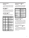
Device Information Menu
(Block 3B)
The Device Information menu is strictly an
informational page. By entering this menu, a
selection of useful information can be viewed
and/or edited. There are a total of ten information
entries:
1. Tag - This 8 character entry can be used as
a unique label that correlates to a field device
label.
2. Descriptor - This entry is a 16 digit field
that can be used to provide any description
desired.
3. Message - This entry is a 32 digit field that can
be used to provide any message desired.
4. Model - This entry displays the model number
of the drive in which the DCM-2 board is
installed. It normally is set at the factory if the
board is installed in a drive. The user can edit
the field if desired.
5. Drive S/N - This entry displays the serial
number of the drive in which the DCM-2 board
is installed. It normally is set at the factory if
the board is shipped in a drive. If the DCM-2
is shipped as a spare or replacement part, the
“Drive S/N” field will be blank. The user can
edit the field if desired.
6. Installed - This is a date entry that is normally
used to indicate the date that the drive or
DCM-2 board was installed. The date format
is mm/dd/yyyy and it can be edited.
7. Setup - This is a date entry that is normally
used to indicate the date that the DCM-2/drive
setup was performed. Although this entry
is viewed and can be edited in the “Device
Information” menu, the user is prompted at the
end of performing a “Setup” to enter a date.
Entering the date at the prompt automatically
updates the date displayed. The date format
is mm/dd/yyyy, and it can be edited.
8. Calibrated - This is a date entry that is
normally used to indicate the date that the
DCM-2/drive was last calibrated. Although
this entry is viewed and can be edited in
the “Device Information” menu, the user
is prompted at the end of performing any
“Calibration” method to enter a date. Entering
the date at the prompt, automatically updates
the date displayed here. The date format is
mm/dd/yyyy, and it can be fully edited.
9. Review - Scrolls through all device information
items, as well as all the other DCM-2 settings,
without accessing each item individually. This
is an excellent tool for quickly determining
how a particular drive is setup. To edit
individual entries, the user must exit "Review"
and proceed to the appropriate menu and
item.
10. Poll Address - This entry can be edited;
however, it is normally set to 0. A polling
address from 1 to 15 can be entered if the
drive resides on a common HART
®
network
with other HART
®
devices.