


6
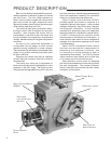
PRODUCT DESCRIPTION
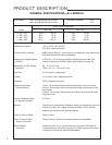
GENERAL SPECIFICATIONS—ALL MODELS
Drive Power 120 V ac single-phase 50 or 60 Hz Allowable Tolerance +10%
240 V ac single-phase 50 or 60 Hz -15%
Max. Current and Power
Model 120 V ac 240 V ac
11-159, -169 .40 A 48 W .20 A 48 W
11-209, -269 .65 A 78 W .33 A 78 W
11-309, -369 .65 A 78 W .33 A 78 W
11-409, -469 3.10 A 400 W 1.55 A 400 W
Operating Conditions -40° to 185°F (-40° to 85°C)
0 to 100% relative humidity
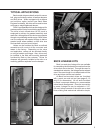
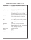
Communication Interface HART protocol (Rev. 5 -- burst mode is not supported), local pushbutton/
LED panel and RS-232 Serial commands.
Demand input Signal Options 4–20 mA (1–5 V dc input is possible with the removal of the "R11"
(DCM-2) resistor located on the DCM-2 board (see diagram on page 78).
Adjustability for Split Range 0%: 0.1 V to 4 V dc
Operation 100%: 0% + 1 V min. to 5 V max.
Step Size 0.15% typical (configurable).
Linearity ±1% of span, max. independent error
Hysteresis 0.25% of span at any point
Demand input Signal Linear: Drive output shaft moves proportionally to the input signal.
Characterization Square: Drive output shaft moves proportionally to the square of the
input signal.
Custom: Drive output shaft moves according to the custom demand
response curve.
Position Feedback Signal 4–20 mA
for Remote Indication
Isolation Demand input and position Feedback signals are isolated from ground
and the ac power line. Signal buffering provides 24 V dc isolation
between the Demand and Feedback signals.
Action on Loss of Power Stays in place
Action on Loss of Input Stays in place or drives to any preset position (configurable).
Signal (Power On)
Stall Protection If the motor tries to run in one direction for more than 300 seconds
(Optional) (configurable from 30 to 300 seconds), the DCM-2 will shut off power
to the motor (feature can be enabled/disabled).