


20
OPERATION
HOUSING
Beck electronic control drives have individual
cast aluminum compartments for each of the
five main components: The control motor, wiring
terminal block, drive train, digital control module,
and control end. Gasketed covers and sealed
shafts make the drives ideally suited to outdoor
and high humidity environments.
Heavy cast mechanical stops built into the
housing are designed to prevent accidental over-
travel damage during manual cycling, and ensure
that proper orientation is maintained between
the output shaft and the feedback system. Drive
travel is centered between the mechanical stops
unless otherwise specified at time of order.
CONTROL MOTOR
The Beck control motor is a synchronous
inductor motor which operates at a constant
speed of 72 RPM or 120 RPM in synchronism
with the line frequency.
Motors are able to reach full speed within 25
milliseconds and stop within 20 milliseconds;
actual starting and stopping times will vary with
load.
Beck motors have double grease-sealed
bearings and require no maintenance for the life
of the motor.
GEAR TRAIN
The gear train is a four-stage reduction, spur
gear drive constructed with only heat-treated alloy
steel and ductile iron gears for durability and long
life.
The drive train consists of the control motor and
Handwheel, reduction gears, main gear, output
shaft, and crank arm. The main gear / output shaft
and third stage gears are common to all units of
a particular drive model. The second and first
stage gears are part of the field-interchangeable
gear module. Different combinations of gear
modules and drive motors determine the drive’s
output torque and timing. See Table 9, page 83
for details.
On all models except the 11-169, the output
shaft is limited by mechanical stops to 108° of
rotation. On model 11-169 drives, the output shaft
is limited by mechanical stops to 98° of rotation.
Optional main gear / output shaft assemblies are
available that permit multi-revolution output rotation.
Mechanical stops are not included on these models.
Mechanical transmission of output shaft position to
the control end is provided by a right angle gear set
driven directly by the output shaft.
SELF-LOCKING
MECHANISM (SLM)
An integral part of every control motor is the
self-locking mechanism. This mechanical device
couples the motor to the gear train and transmits
full motor torque when rotated in either direction.
When the motor is de-energized, the SLM
instantaneously locks and holds the output shaft
in position.
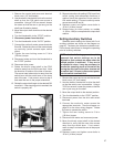
HANDWHEEL
Every Beck control drive is furnished with a
Handwheel to permit manual operation of the valve or
damper without electrical power. Its solid construction
design includes no spokes or projections, and turns at
a safe, slow speed. The Handwheel is located at the
rear of the control motor housing. The Handwheel is
coupled directly to the motor shaft and rotates when
the motor runs. Manual operation of the Handwheel
(with electric Handswitch in “STOP” position) turns
the motor and the rest of the drive train without
incorporating a clutch.
HANDSWITCH
A local electric Handswitch is provided on Beck
drives to permit operation at the valve or damper,
independent of the controller. As a safety feature,
the Handswitch is designed so that the controller can
operate the drive only when it is in the “AUTO” position.
The sequence of the Handswitch is: “AUTO”, “STOP”,
“CW”, “STOP”, “CCW”. When the Handswitch
is turned fully clockwise, “AUTO” should be
indicated.
In the “AUTO” position, two contacts are closed
and the DCM-2 completes the control circuit.
In the “CW” or “CCW” positions, contacts are
closed to operate the drive independently of the
controller.
In the “STOP” position, all contacts remain open.
To prevent Handswitch initiated motion, remove
the jumper between terminals A and C. CAUTION:
AC power to the drive must be turned off before
removing the jumper.
SWITCHES
Two over-travel limit switches and up to
four optional auxiliary switches are provided on
Beck drives. Switch cams are clamped onto
the control shaft which rotates in relation to the
output shaft. Cam position is field-adjustable.
Switches are rated 6 A, 120 V ac. All auxiliary
switch connections are made on the terminal
block.