


25
All Beck drives are shipped completely
calibrated to the customer’s specifications that
were written into the equipment order and are
ready to be installed. If the need arises to change
the drive calibration, first confirm that the drive is
installed as specified and operating properly before
proceeding with the change.
Position reference and demand calibration are
performed using the DCM-2 customer interface
panel, but may also be configured using the HART
or Serial interface. Calibration of over-travel limit
and auxiliary switches must be performed using
the procedure beginning on page 26.
CALIBRATION PRIORITY
Models 11-159, -209, -309 & -409
Standard Group 11 drives are equipped with
fixed, non-adjustable, built-in mechanical stops.
All output shaft rotation must occur within these
stops, which are approximately 108° apart.
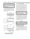
The over-travel limit switches are used to limit
the electrical control range of the drive. These
switches are cam operated and are set slightly
wider apart then the drive’s intended full range
of electronic operation (typically 100°). The limit
switches are positioned to provide an electrical
overtravel protection (typically 101°).
If the drive is short-stroked—i.e., the full travel
rotation from 0–100% is reduced to less than the
standard 100° rotation (see page 30)—it may be
desirable to reset the over-travel limit switches
(see page 26). If the limit switches are not reset,
Handswitch operation of the drive (CW, CCW)
will still result in the original full range of travel.
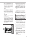
It is best to calibrate the drive and then set the
limit switches when short-stroking the drive. The
switches should be set just outside the calibrated
range to avoid tripping the switch at the 0% and
100% positions.
The auxiliary switches are also cam operated,
but have no affect on drive and DCM-2 operation.
Therefore, the auxiliary switches can be adjusted
at any time without affecting performance or
calibration.
Models 11-169, -269, -369 & -469
Standard Group 11 drives are equipped with
fixed, non-adjustable, built-in mechanical stops.
All output shaft rotation must occur within these
stops, which are approximately 108° apart; except
for the 11-169 stops, which are 98° apart.
The over-travel limit switches are used to limit
the electrical control range of the drive. These
switches are cam operated and are set slightly
wider apart then the drive’s intended full range
of electronic operation (typically 90°). The limit
switches are positioned to provide an electrical
overtravel protection (typically 91°).
If the drive is short-stroked—i.e., the full travel
rotation from 0–100% is reduced to less than the
standard 90° rotation (see page 30)—it may be
desirable to reset the over-travel limit switches
(see page 26). If the limit switches are not reset,
Handswitch operation of the drive (CW, CCW) will
still result in the original full range of travel. Because
the over-travel limit switches define the maximum
electrical drive range, if they are to be reset, they
should be adjusted before performing DCM-2
(demand and position) calibration procedures.
The auxiliary switches are also cam operated,
but have no affect on drive and DCM-2 operation.
Therefore, the auxiliary switches can be adjusted
at any time without affecting performance or
calibration.
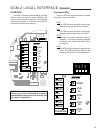
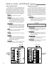
DCM-2 LOCAL INTERFACE Calibration