


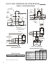

18
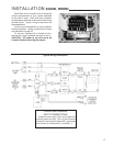
INSTALLATION START-UP
LINKAGE REQUIREMENTS
(If Applicable)
In most applications, the best control will result
when the linkage is adjusted so that the full 100°
angular travel of the Beck drive output shaft is
used, even though the valve or damper may travel
less than 100°.
The general requirements for a good linkage
are:
1. It must be rigid enough to carry the link thrust
without bending or deforming.
2. It must have a built-in means of adjustment so
that the length of the connecting link can be
changed a small amount.
3. Rod end bearings, similar to those furnished
on the Beck crank arm, should be used at both
ends of the connecting link. This type of device
permits small angular misalignments and helps
prevent binding of the linkage.
4. The radius of the Beck crank arm must be
calculated so that it will move the valve or
damper lever through the correct arc as the
lever travels from 0° to 100°.
5. The drive and valve / damper shafts must be
parallel and the linkage should be in a plane
perpendicular to the shafts.
The following procedure is recommended to
couple the linkage between the Beck drive and
the driven shaft (this procedure assumes that the
Beck drive will open the damper/valve in response
to an increasing signal) :
1. Position the driven shaft to the closed
position.
2. Set the driven shaft lever to its predetermined
starting angle in relation to the driven shaft and
output shaft centerline.
3. Remove the rod end from the Beck crank arm.
Attach to the connecting link.
4. Adjust the connecting link to the predetermined
length.
5. Connect the connecting link to the driven lever
at the predetermined radius.
6. Loosen the Beck crank arm clamping bolts.
7. Position the drive’s output shaft to correspond
with the driven shaft's fully closed position.
8. Set the crank pin on the Beck crank arm to the
predetermined radius.
9. Swing the crank arm into position to assemble
the rod end to the crank arm crank pin.
10. Tighten the crank arm clamp bolts to the torque
recommended on pages 8, 10 and 13.
11. Tighten the coupling and rod end jam nuts.
12. Lubricate rod end bearings.
13. Carefully move the drive’s output shaft to
correspond with the driven shaft's fully open
position. Check that no binding occurs between
the linkage, crank arm, driven shaft lever, and
surrounding obstructions. Also, observe that
the driven shaft rotates the proper amount.
Ensure that the drive reaches the proper limit
and shuts off. If binding in the linkage occurs
due to too much travel of the driven lever,
reduce the crank arm radius on the Beck drive
rather than adjusting the connecting link length.
Return to step 5 and repeat adjustments.
To adjust the linkage length, alter the thread
engagement in the couplings. The couplings have
right- and left-hand threads, so it is not necessary to
disconnect the ends to make a length adjustment.
The stud threads must be engaged 1.2 diameters
deep into the rod ends. Make adjustments by
altering thread engagement in couplings only. Be
careful not to expose more than 7” (178 mm) of
stud between rod end and coupling.
Once again, check operation to determine that
no binding occurs between linkage and crank arm
or valve / damper lever arm. Surrounding objects
must not interfere.
Do not change limit switch settings to obtain
desired valve or damper travel. This shortens
the travel of the feedback device and reduces the
control resolution, repeatability, accuracy of the
drive, and available torque.
For an input control signal change, do not
adjust the linkage. Refer to the Calibration section
of this manual.
Link-Assist™
The Beck Link-Assist™ computer program
optimizes the linkage configuration for your load’s
torque characteristics to help you select the
minimum drive size for your application. Contact
your Beck Sales Engineer to take advantage of
Beck’s Link-Assist™ program.
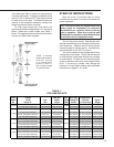
Linkage Kits Available
Standard Beck linkage kits are made to
accommodate a wide variation in linkage lengths
without requiring modification of end fittings. This
adaptability makes it possible to order the essential
linkage end connections even though the exact
linkage length may not be known until the valve /
damper and drive are mounted in place.
Each linkage kit includes the essential
pipe linkage end connections, rod end, and all
necessary hardware. Schedule 40 pipe is not
included and must be cut to length and threaded