


31
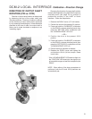
DIRECTION OF OUTPUT SHAFT
ROTATION (CW vs. CCW)
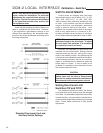
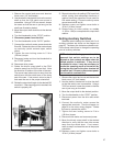
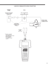
Direction of output shaft rotation is determined
by observing the end of the output shaft (see
illustrations below). Direction of rotation is defined
as the direction of output shaft rotation produced
by an increasing Demand signal. Unless otherwise
specified at the time of order, the output shaft is
factory set to rotate clockwise in response to an
increasing signal.
Changing the direction of output shaft rotation
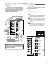
is easily accomplished using the DCM-2 customer
interface panel (see page 23 for location of
pushbutton controls) or the HART or Serial
interface. Follow the steps below.
1. Remove the DCM-2 cover (1/2” bolt heads).
2. Position the drive at the present 0% position.
3. Press and hold the “CALIBRATE” pushbutton
on the DCM-2 customer interface panel, then
press the “SET POS 100%” pushbutton until
the “ACKNOWLEDGE” LED is lit.*
—OR—
2. Position the drive at the present 100%
position.
3. Press and hold the “CALIBRATE” pushbutton
on the DCM-2 customer interface panel, then
press the “SET POS 0%” pushbutton until the
“ACKNOWLEDGE” LED is lit.*
4. Ensure the drive operates as desired.
5. Replace the DCM-2 cover and tighten the
cover bolts to 10 lb-ft (14 N•m) torque. Reset
travel index.
* If the “ACKNOWLEDGE” LED does not light, but
the “POSITION” LED does light, the signal is out
of acceptable range and was not accepted by the
DCM-2.
NOTE: When either of the above procedures is
performed, both the 0% and 100% positions are
automatically set.
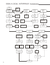
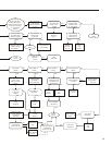
DCM-2 LOCAL INTERFACE Calibration - Direction Change