


19
START-UP INSTRUCTIONS
After the drive is mounted and its wiring
connections are made, it is ready to be tested for
proper operation.
NOTE: All Beck drives are shipped from the
factory ready for installation; no electrical
adjustments are required before placing
them in operation. Each drive is set up and
calibrated to the customer’s specifications that
were written into the equipment order.
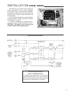
Turn on the power supply. Operate the drive
with the Handswitch and run it through its full stroke,
both directions. Observe that the driven device
travels through its desired stroke. If satisfactory,
set Handswitch to the “AUTO” position.
Turn on the controller and operate the drive by
varying the control signal. Check that the damper
or valve strokes in the proper direction for a change
in control signal. If it does not, first check for proper
wiring connections and verify control signal at the
drive. If the wiring is correct, then change the
direction of output shaft rotation (see applicable
instructions on page 31, 51 or 69).
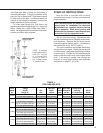
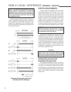
in the field (see Table 1, below, for instructions to
calculate pipe length). To simplify installation of the
pipe link, the kit accepts NPT right-hand threads
on both ends of the pipe. Left-hand threads are
internal to the linkage kit assembly, making final
length adjustments quick and easy.
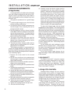
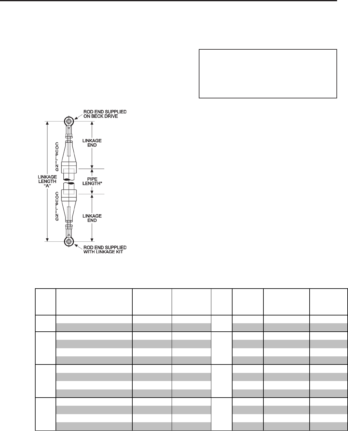
To order pipe linkage kits, first obtain the
approximate overall linkage length “A” in the figure
below. Select the kit part number from Table 1,
below. For lengths beyond those listed in the table,
contact your Beck sales engineer.
TABLE 1:
PIPE LINKAGE KITS
*NOTE: To calculate
length of pipe required,
subtract “Length
of 2 Linkage Ends”
(shown in Table 1)
from Linkage Length
“A” (shown at left).
Beck Rod Length of 2
Drive Linkage Min. Pipe End Beck Pipe Linkage Ends
Model Length Pipe Nipple Thread Linkage Kit (Total Adj. Approx.
No. Range "A" Size Length (UNF) Part No. ±1 1/2"(38 mm)) Weight
11-159
22–84" (559–2 134 mm) 1" (25 mm) 1 1/2" (38 mm)
1/2-20
20-1730-05 20 1/2" (521 mm) 5 lbs (2 kg)
31–120" (787–3 048 mm) 1 1/2" (38 mm) 1 3/4" (44 mm) 20-1740-06 29 1/4" (743 mm) 9 lbs (4 kg)
11-209
22–45" (559–1 143 mm) 1" (25 mm) 1 1/2" (38 mm)
1/2-20
20-1730-05 20 1/2" (521 mm) 5 lbs (2 kg)
31–84" (787–2 134 mm) 1 1/2" (38 mm) 1 3/4" (44 mm) 20-1740-06 29 1/4" (743 mm) 9 lbs (4 kg)
33 1/4–120" (845–3 048 mm) 2" (51 mm) 2" (51 mm) 20-1750-05 31 1/4" (794 mm) 13 lbs (6 kg)
37–120" (940–3 048 mm) 2 1/2" (64 mm) 2 1/2" (64 mm) 20-1760-05 34 1/2" (876 mm) 22 lbs (10 kg)
11-309
22 1/2–36" (572–914 mm) 1" (25 mm) 1 1/2" (38 mm)
5/8-18
20-1730-06 21" (533 mm) 5 lbs (2 kg)
31 1/2–72" (800–1 829 mm) 1 1/2" (38 mm) 1 3/4" (44 mm) 20-1740-07 29 3/4" (756 mm) 9 lbs (4 kg)
33 3/4–96" (857–2 438 mm) 2" (51 mm) 2" (51 mm) 20-1750-06 31 3/4" (806 mm) 13 lbs (6 kg)
37 1/2–120" (953–3 048 mm) 2 1/2" (64 mm) 2 1/2" (64 mm) 20-1760-06 35" (889 mm) 22 lbs (10 kg)
11-409
23 1/4–34" (590–864 mm) 1" (25 mm) 1 1/2" (38 mm)
3/4-16
20-1730-07 21 3/4" (552 mm) 5 lbs (2 kg)
32 1/4–48" (819–1 219 mm) 1 1/2" (38 mm) 1 3/4" (44 mm) 20-1740-08 30 1/2" (775 mm) 9 lbs (4 kg)
34 1/2–72" (876–1 829 mm) 2" (51 mm) 2" (51 mm) 20-1750-07 32 1/2" (826 mm) 13 lbs (6 kg)
38 1/4–120" (972–3 048 mm) 2 1/2" (64 mm) 2 1/2" (64 mm) 20-1760-07 35 3/4" (908 mm) 22 lbs (10 kg)