


57
DEMAND SIGNAL
CALIBRATION
DCM-2 boards are designed to accept a
4–20 mA (or 1–5 V dc) analog Demand signal.
Narrower spans within this range can also
be accommodated for split range operation
(see explanation following). The input comes
calibrated from the factory for the full range
unless otherwise specified. It is not necessary
to calibrate the Demand input when the drive is
installed.
If the Demand must be changed, it is
accomplished using a HART comunication
device.
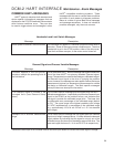
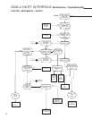
First, navigate to the Configuration menu.
Select the Demand Setup submenu. Through
this submenu, the Demand range limits and
curve specifications may be changed. Online
help is available through the communication
device.
DCM-2 HART INTERFACE Calibration - Demand
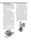
Split Range Operation
It is sometimes desirable or necessary to have
more than one final control element controlling
a single process. Often, this type of control
strategy requires that two to four Beck drives
each respond to different portions of one 4–20
mA Demand signal from the control system.
This type of operation is called split range
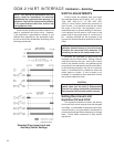
operation. For example, consider the most
common split range scenario—two drives split
ranged for 50% of the 4–20 mA Demand signal
input. Both drives are wired in parallel to receive
the same 4-20 mA signal (note that the total loop
resistance should be 250 Ohms as specified by
the HART
®
communications protocol. The 250
Ohm R11
resistor (see DCM-2 illustration on page
78) must be removed from one of the two drive
DCM-2 boards to allow HART
®
communications.
If more than two drives are split ranged, the R11
resistor must be removed from all the DCM-2
boards but one), but each drive’s interpretation
of the signal must be different. One drive must
interpret 4–12 mA as 0–100% Demand, and
one drive must interpret 12–20 mA as 0–100%
Demand. This requires that the drives have
different Demand signal calibrations.
Split-ranging is easily accomplished by
determining the break points (12 mA in the
example above) and using a HART communication
device.
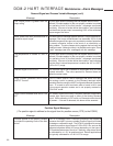
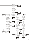
First, navigate to the Configuration menu.
Next, select the Demand Setup submenu.
Change appropriate Demand range limit
accordingly. In the example above, one drive's
upper Demand range (DemRngUpr) would be
changed from 20.00 mA to 12.00 mA; and the
other drive's lower Demand range (DemRngLwr)
would be changed from 4.00 mA to 12.00 mA.
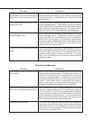
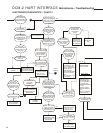
NOTE: Ensure that the L.O.S. (Loss of
Demand input signal) settings of the drives
are appropriate for the new configuration.
This would involve changing the appropriate
Demand LOS limits (DemLimLwr or
DemLimUpr). Typically, these settings are -5%
and 105% of the Demand range. See page 21
for a description of the LOS function.