


17
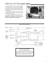
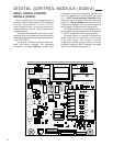
INSTALLATION SIGNAL WIRING
Each Beck drive is custom built to match the
control requirements of your system specified
at the time of order. Each drive has a specific
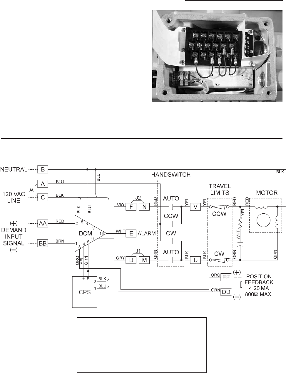
wiring diagram attached to the inside of the wiring
terminal cover. Typical wiring connections are
described below.
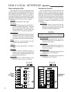
A drive can be ordered with up to four optional
auxiliary switches. Wiring connections for these
are described on page 26.
To prevent Handswitch initiated motion,
remove the jumper between terminals A and C.
CAUTION: AC power to the drive must be
turned off before removing the jumper.
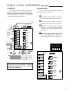
Typical Wiring Connections
POWER AND DEMAND
INPUT CONNECTIONS
Customer must supply 120 V ac to power the
drive and control circuitry. 120 V ac line connects
to terminal C and neutral to terminal B. Input signal
wires connect to terminals AA (+) and BB (–).