


Operations Overview 2-2
B1272M001
BARNETT ENGINEERING LTD. ProTalk Cv2
HARDWARE
INPUTS
8
INPUTS
8
OUTPUTS
POINTS
UP TO 30 INPUTS OR OUTPUTS
GROUP
1
CELL PHONE
HARDWARE
OUTPUTS
GROUP
6
DIRECTORY
A
DIRECTORY
F
DIALOUT
COMMANDS
CONTROL
COMMANDS
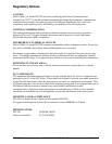
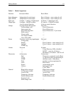
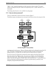
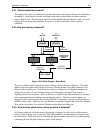
Figure 1
Cv2 Block Diagram - Advanced Mode
“High” or Low” appended depending on which setpoint has been exceeded. The actual
reading, including decimal place notation and engineering units, is spoken when the Cv2 is
interrogated.
The latching alarm function is also available for analog inputs.
2.1.3 How are alarms processed?
The way in which the Cv2 processes alarms is shown in Figure 1.
The hardware input and output ports are activated in the Points section to become part of the
monitoring and control process. There are 30 points which can be referenced to any of the I/O
ports. This allows an analog input to be used by more than one point and monitored for
multiple setpoints, as would be the case where minor and major alarms are required.
If you do not want all of the points to generate the same response when they detect alarms,
they can be placed into different groups. Six groups are available, each with independent
timers and control codes. When a group detects an alarm condition in one of its assigned
points, it executes the sequence of actions found in the current directory. A group can use any
of the six directories to perform the call out function, plus the directory selection can be
changed by using the shift control feature.