


Operations Overview 2-6
B1272M001
BARNETT ENGINEERING LTD. ProTalk Cv2
ALARMS
8
INPUTS
8
OUTPUTS
CELL PHONE
OUTPUTS
DIRECTORY
A
DIRECTORY
B
DIALOUT
COMMANDS
CONTROL
COMMANDS
5
HARDWARE
CONTROLLED
3
USER
CONTROLLED
ACKNOWLEDGE
INTERROGATE
ACCESS
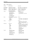
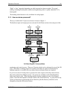
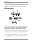
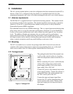
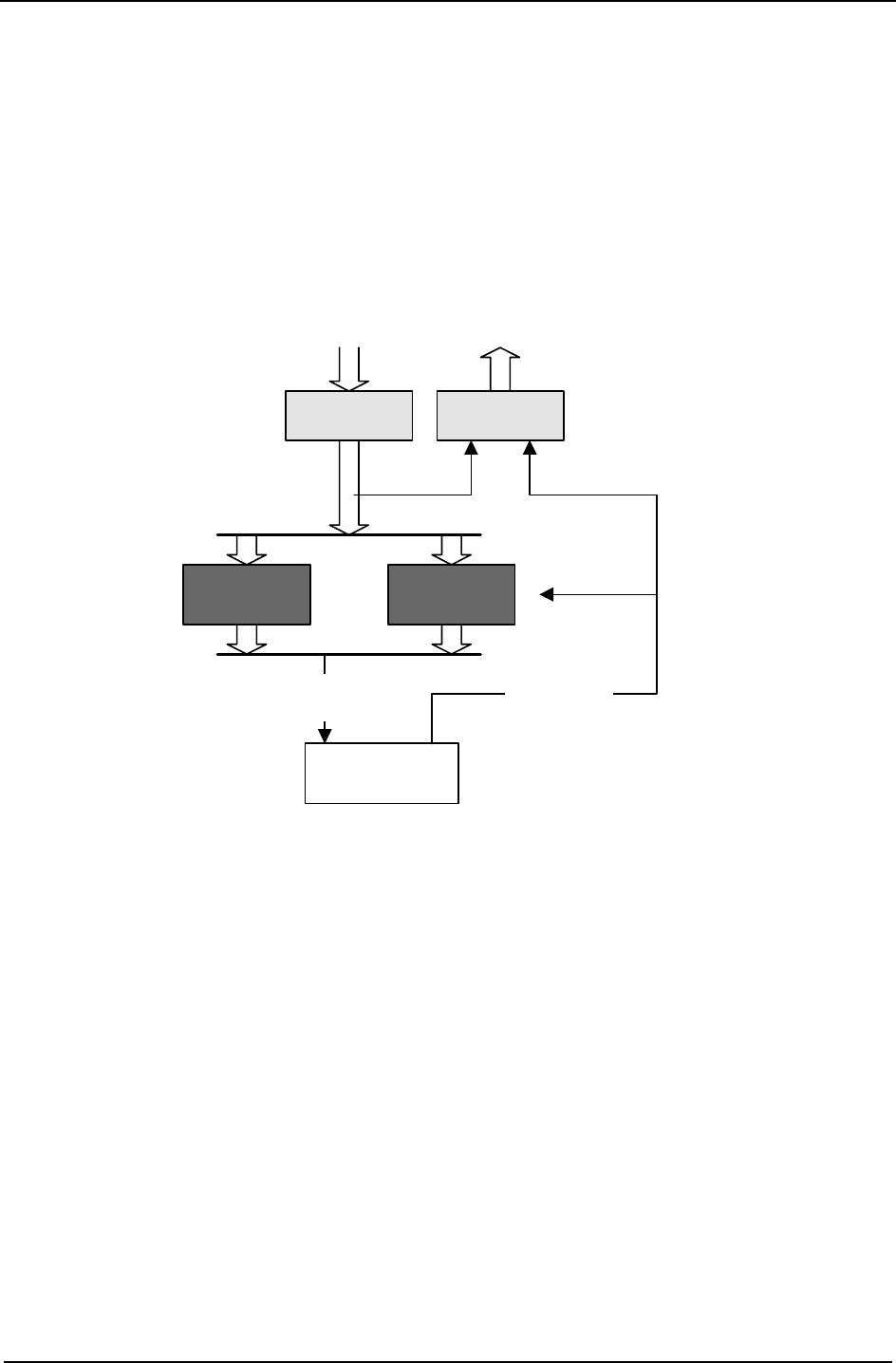
Figure 2 Cv2 Block Diagram - Basic Mode
2.2.1 What constitutes an alarm?
The signal at the input is conditioned by a debounce timer that ensures the level is valid before
accepting it. An alarm has normal and alarm states that can be defined as either when the
input is high or low. After the input signal has been qualified by the debounce timer, it can be
registered as an alarm when the input is active, or it can be latched to detect a pulsed
condition.
2.2.2 How are alarms processed?
The way in which the Cv2 processes alarms in Basic mode is shown in Figure 2. The eight
inputs can be activated in the Alarms section by selecting them to use either Directory A or
Directory B for calling out. Each directory can have a unique list of telephone numbers for
calling out as well as its own Acknowledge code, Interrogate code and Cycle timer for
repeating the call out sequence. When a directory is edited in the Advanced mode it can have
more commands than just dialing and speaking the alarms. The three control outputs are
activated in the Control section by selecting On/Off or momentary operation and entering the
DTMF control codes. There are also five hardware controlled outputs that are used to indicate
New alarm, Any alarm, Ack received, Modem carrier detect and Ring out.
2.2.3 What actions should occur when an alarm is detected?
All alarm conditions will be processed by placing a sequence of calls on the cellular phone
until an Acknowledge code is received. The called numbers are determined by entries in the
two directories. Each call consists of dialing the phone number followed by a verbal message
containing the Site ID phrase then any active alarm phrases.