


Installation 3-1
B1272M001 BARNETT ENGINEERING LTD. ProTalk Cv2
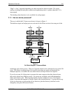
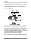
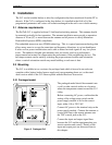
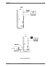
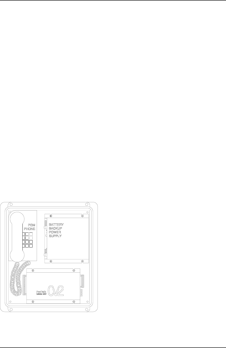
Figure 3 Packaged Cv2
3 Installation
The Cv2 can be installed before or after the configuration has been transferred from the PC to
the unit. If the Cv2 is configured in the shop before it is installed in the field, all of the
programmed parameters and voices will remain unchanged in the unit’s non-volatile memory.
3.1 Antenna requirements
The ProTalk Cv2 is supplied with an 8" dual band articulating antenna. This antenna should
be mounted vertically for best operation. The antenna installation must provide a separation
distance of 20 cm (8") or more between the antenna and all persons to satisfy Maximum
Permissible Exposure (MPE) compliance.
The embedded transceiver uses CDMA technology. This is a spread spectrum technology that
allows many users to occupy the same time and frequency allocations in a given band/space.
It relies on low power transmissions and is able to detect received signals at very low power
levels. The addition of higher gain antennas does not usually result in a performance
improvement but instead can compromise the performance of the neighboring devices. The
best improvements can be made by selecting the proper antenna location and orientation
where a vertical orientation outside any metal building or enclosure is best.
3.2 Mounting
The Cv2 is available in two versions: the packaged unit which is housed in an enclosure
complete with a battery backed power supply and a programming phone set, or the stand-
alone version which is the Cv2 alarm reporter without the above accessories.
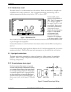
3.2.1 Packaged model
The packaged model should be mounted onto
a wall or other vertical surface in a location
where the temperature cannot exceed the Cv2
rating.
Before connecting AC power, confirm that the
setting of the voltage range switch on the
power supply module is set for the correct
input, either 110 or 220 VAC.
Connect AC power to the terminal strip on the
power supply module. Connect the antenna or
coaxial feed line to the remote antenna onto
the TNC coaxial jack on the Cv2.
Connect the input and output signal lines
between the Cv2 and the equipment that you
want to monitor and control. Details of the
input and output ports are discussed later in
this chapter.