


Installation 3-2
B1272M001 BARNETT ENGINEERING LTD. ProTalk Cv2
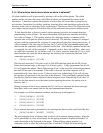
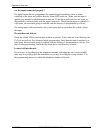
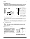
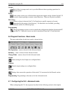
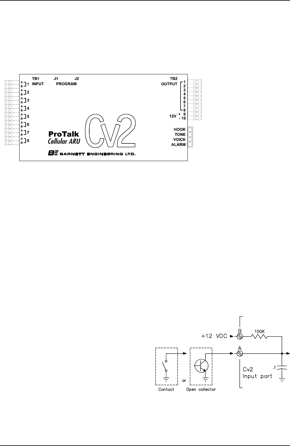
Figure 4 Stand-alone Cv2
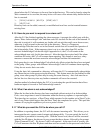
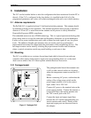
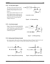
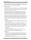
Figure 5 Ground Closure Input Wiring
3.2.2 Stand-alone model
The stand-alone Cv2 can be mounted on a flat surface. Make sure that there is enough room
around the unit to make connections. The environment should be clean and dry, with an
ambient temperature that does not go below -30
o
C or above +50
o
C.
Connect a DC power
source to the terminals on
TB2. The Cv2 requires up
to 1.2 Amps to operate;
the supply should be sized
accordingly. Input power
to the unit is protected by
a Polyswitch current
limiter. If a fault develops
in the CV2, this switch
will become a high
resistance to prevent
damage to the equipment
or the power supply. Once
this switch has been activated, the fault must be removed before it will reset and allow current
to pass through to the equipment.
Connect the antenna or coaxial feed line to the remote antenna onto the SMA coaxial jack on
the Cv2.
Connect the input and output signal lines between the Cv2 and the equipment that you want to
monitor and control. Details of the input and output ports are discussed in the next section.
3.3 Input port connections
The input ports can be connected to a variety of contact or voltage sources for monitoring
purposes. Select a wiring configuration that matches your alarm source from one of the
following arrangements:
3.3.1 Ground closure alarm signal
For alarm sources that appear as a ground
closure, either through a mechanical contact
or an open collector driver, the input should
be wired according to Figure 5. If the input
is normally open and goes to ground during
an alarm condition, program the Hardware
section for this input as “Normally High”. If
the reverse is true, set the input to “Normally
Low”.