


General Information 1-3MN894
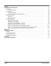
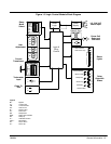
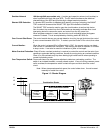
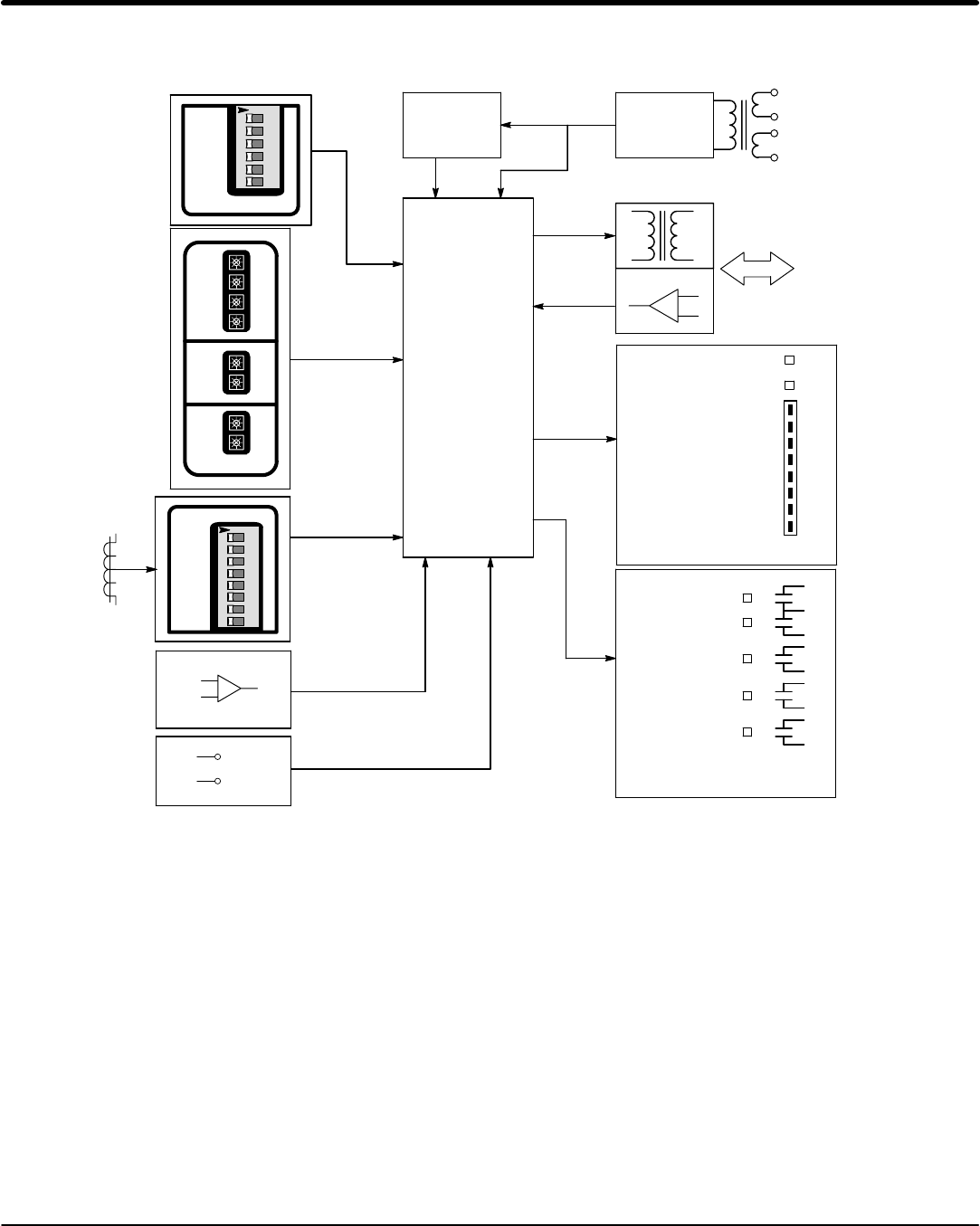
Figure 1-2 Logic Control Module Block Diagram
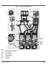
1
2
3
4
5
6
123456
O
N
OFF ONS2
RDD
CM
OC
TACH
CL
BP
Ramp
Mode
Select
Logic &
Firing
Control
CM
PF
MIN MAX
R
U
N
RD
TD
S
T
O
P
CL
PT
RU
TU
S
T
A
R
T
User
Adjustment
Control Power
Overcurrent Trip
Current Monitor
Motor Power
400
300
200
100
0
%FLA
M
O
T
O
R
C
U
R
R
E
N
T
Status
Lights
C
C
U
R
R
E
N
T
A
L
I
B
R
A
T
I
O
N
OFF ONS1
1
2
3
4
5
6
7
8
12345678
O
N
Current
Transformer
Tachometer
Input
+
-
Reset
Logic
Power
Supply
115 /230 VAC
Power Input
+
-
Gates & Sync.
Power Cell
Gates and
Cathodes
Relay
Outputs &
Status
4
5
PWR
OC
1
2
3
6
7
8
9
10
11
12
13
Ramp End
Shunt Trip
Start/Run
Close To Run
Close To
Run
x
x
Legend:
BP - Bypass
CL - Current Limit
CM - Current Monitor
OC - Overcurrent
PF - Power Factor
PT - Pulse Time
RD - Ramp Down
RDD - Ramp Down Disable
RU - Ramp Up
S1 − Calibration Switch
TACH - Tachometer
TD - Torque Down
TU - Torque Up