


General Information 1-5MN894
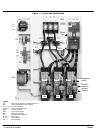
Snubber Network 160 through 840 amp models only. A resistor and capacitor series circuit (snubber) is
wired in parallel with each disk type SCR. The RC network enhances the electrical
characteristics of the SCR and provides high voltage transient protection.
Shorted SCR Detection: If a shorted SCR condition is detected while starting, running or stopping, the SHUNT
TRIP contact will close and the SHUNT TRIP light will indicate the condition.
The SHUNT TRIP contact is used to open the circuit breaker via a shunt trip device.
Also, the shunt trip contact from the LCM module can be used to activate other circuit
interrupting device to remove the motor and control from the AC power line.
When a bypass contactor is used, the shunt trip circuit is disabled when the bypass
contactor is closed. This is accomplished by switching switch BP S2-6 On.
Over Current Shut Down: The control module has an over current detection circuit to trip and shut down the control
if motor current exceeds 450% FLA. To restart, open the Close To Run circuit, then close
it.
Current Monitor: When the motor is at speed (End of Ramp light is “ON”), the current monitor can detect
over current or overload motor conditions. This warning can alert an operator or be used
to stop a motor. It can also be used for indications of jams or blockages.
Motor Overload Protection: Class 30 motor overload protection is required to protect the control and the motor from
repetitive or extended starting conditions, as well as running during an overload condition.
Class 10 or 20 overloads may trip when starting high inertia loads or when operating in
current limit starting mode.
Over Temperature Switch: Power cells have over temperature switches to detect an overheating condition. The
switch is an isolated bimetallic, normally closed contact. If loss of cooling causes a power
cell to overheat, the temperature switch contact will open and shut down the control
circuit.
Note: When a temperature switch opens, the control shuts down. It must be reset
manually to restart the control.
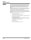
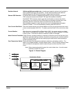
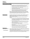
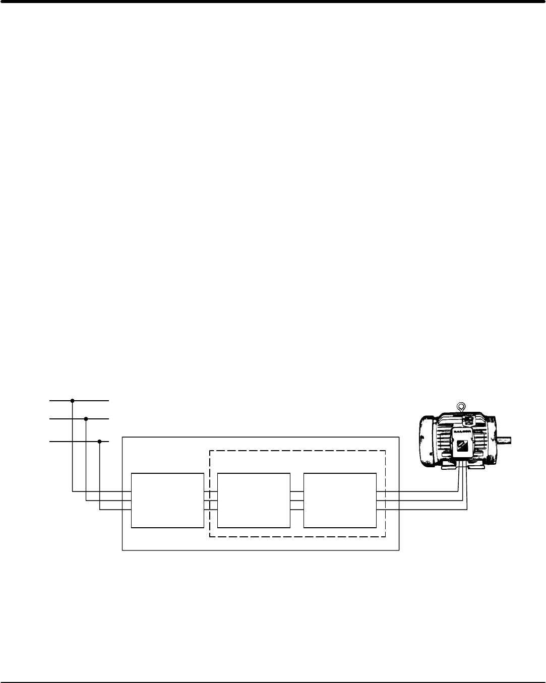
Figure 1-3 Starter Diagram
L1
L2
L3
Combination Starter
Non-Combination Starter
Overload
Relay
Soft
Start
Control
(Control only)
Circuit
Breaker or
Fusible
Disconnect