


Appendix A
Reference Information
Appendix A-1MN894
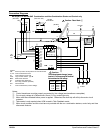
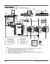
Glossary
BP Bypass Contactor
CC Current Calibrator
CCW Counterclockwise
CL Current Limit
CM Current Monitor
CS & RS Resistor & Capacitor series
circuit
CUR MON Current Monitor
CT Current Transformer
CW Clockwise
FLA Full Load Amperes (Motor)
LCM Logic Control Module
LED Light Emitting Diode
MCP Motor Circuit Protector
MOV Metal Oxide Varistor
MTR PWR Motor Power
OC Over Current Shutdown
OL Overload Relay
PC Power Cells
PF Power Factor Correction
PIV Peak Inverse Voltage
PT Starting Pulse Time
PWR Power
Ramp End End of Voltage Ramp
RD Ramp Down Time
RDD Ramp Down Disable
RMS Root Means Squared
RU Ramp Up Time
SCR Silicon Controlled Rectifier
Shunt Trip Shorted SCR Detection
SSC Soft Start Control
TACH Tachometer
TD Reduced torque value at start
of Ramp Down Time
TU Initial starting torque at Ramp
Up Time
X Control Transformer
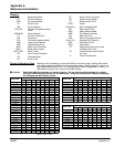
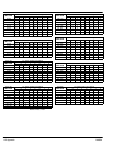
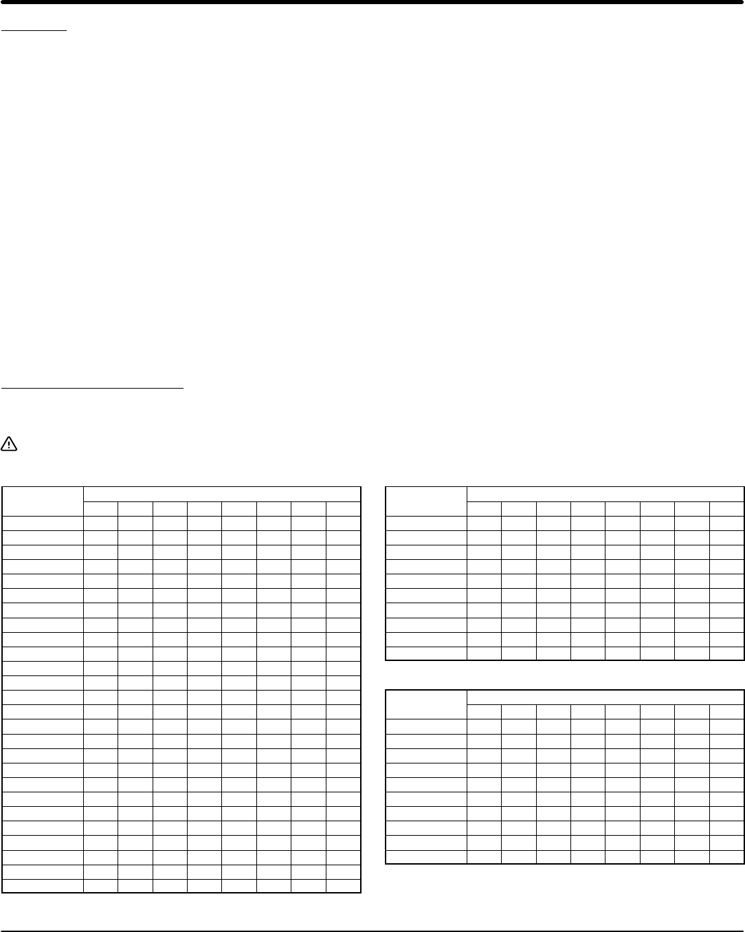
Current Calibration Chart Settings for S1 are based on motors with 600% locked rotor amps. Motors with locked
rotor amps greater than 600% should use a higher setting. Baldor Super-ER motors on
high inertia loads should be set 1 or 2 settings higher than the suggested S1 setting. If a
load takes too long to start, use the next higher setting.
Caution: Select the table that matches you starter size only. Do not use the switch settings for a starter
size that is different than the one you are setting up. Using the wrong switch setting can damage
the Multipurpose Soft Starter control.
Size 008
M t FLA
S1 Switch Position and Setting
Motor FLA
1 2 3 4 5 6 7 8
1.0−1.1 1 1 1 0 0 0 0 1
1.1−1.2 0 0 0 0 1 0 0 1
1.2−1.3 0 0 0 1 1 0 0 1
1.3−1.4 0 0 0 0 0 1 0 1
1.4−1.5 0 1 1 0 0 1 0 1
1.5−1.6 0 0 1 1 0 1 0 1
1.6−1.7 1 0 0 0 1 1 0 1
1.7−1.8 0 1 1 0 1 1 0 1
1.8−1.9 0 0 1 1 1 1 0 1
1.9−2.1 0 0 0 0 0 0 1 1
2.1−2.3 1 0 1 0 0 0 1 1
2.3−2.5 0 1 0 1 0 0 1 1
2.5−2.7 0 1 1 1 0 0 1 1
2.7−3.0 0 1 0 0 1 0 1 1
3.0−3.3 0 1 1 0 1 0 1 1
3.3−3.6 1 0 0 1 1 0 1 1
3.6−3.9 0 0 1 1 1 0 1 1
3.9−4.4 0 0 0 0 0 0 1 1
4.4−4.8 1 1 0 0 0 1 1 1
4.8−5.2 1 0 1 0 0 1 1 1
5.2−5.6 1 1 1 0 0 1 1 1
5.6−6.0 1 0 0 1 0 1 1 1
6.0−6.4 0 1 0 1 0 1 1 1
6.4−6.8 0 0 1 1 0 1 1 1
6.8−7.4 0 1 1 1 0 1 1 1
7.4−8.0 1 1 1 1 0 1 1 1
Note: 0=Off, 1=On
Size 016
M t FLA
S1 Switch Position and Setting
Motor FLA
1 2 3 4 5 6 7 8
6.0−6.5 1 0 0 0 0 1 1 1
6.5−7.0 0 0 1 0 0 1 1 1
7−8 1 1 1 0 0 1 1 1
8−9 1 0 0 1 0 1 1 1
9−10 1 1 0 1 0 1 1 1
10−11 1 0 1 1 0 1 1 1
11−12 1 1 1 1 0 1 1 1
12−13 0 0 0 0 1 1 1 1
13−14 0 1 0 0 1 1 1 1
14−16 1 1 0 0 1 1 1 1
Size 030
M t FLA
S1 Switch Position and Setting
Motor FLA
1 2 3 4 5 6 7 8
12−13 1 0 0 0 0 1 1 1
13−14 1 1 0 0 0 1 1 1
14−15 1 0 1 0 0 1 1 1
15−16 1 1 1 0 0 1 1 1
16−18 1 0 0 1 0 1 1 1
18−20 1 1 0 1 0 1 1 1
20−22 1 0 1 1 0 1 1 1
22−24 0 1 1 1 0 1 1 1
24−27 0 0 0 0 1 1 1 1
27−30 0 1 0 0 1 1 1 1