


1-2 General Information MN894
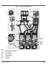
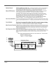
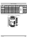
Figure 1-1 Layout and Identification
CB
L1 L2 L3
T1 T2 T3
CT4
CT3
CT2
CT1
CPT
MOV
PC1 PC2 PC3
Fan Fan
LCM
F1
F2
F3
TB1
OL
GND
Overtemperature
Switch
R1
R2
Fan
Snubber
Capacitor
Snubber
Resistor
Shunt
Trip
Legend:
CB - Motor Circuit Protector or fusible disconnect
CPT - Control transformer (control voltage)
CT1, 2, 3, 4 - Current Transformer
F1, F2, F3 - Control transformer fuses
GND - Ground connection
LCM - Logic control module
MOV - Metal oxide varistors
OL - Overload relay (electronic)
PC1, 2, 3 - Power Cell
R1, R2 Control Relays
TB1, 2 - Terminal block