


3-6 Operation MN894
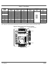
Indicators
Power On The PWR light indicates that power is supplied to the internal power supply of the control.
WARNING: If the power light is not illuminated, it does not necessarily mean
that the line voltage is off. Electrical shock hazard may exist.
Measure the voltage at the line terminals before service.
Over Current OC over current shutdown LED. If the control shuts down due to an over current
condition (motor current is greater than 450% FLA), the OC light will be on. To restart the
control, press stop, then start; or open the close to run circuit, then close it.
Motor Current The Motor Current display is a 10 segment bar graph representation of motor current
from 0 to 400% FLA. Used to check ramp up, run and ramp down current conditions
while the control is in operation.
Summary of Start and Stop Sequences
To Start the Motor: Close 12 - 13 (Close to Run) and the following occurs:
1. 10 - 11 close to confirm start command.
2. 2 - 3 close when power is applied to motor. Ramp up cycle begins.
3. 6-7 close at the end of ramp up cycle.
To Stop the Motor: Open 12 - 13 (Close to Run) and the following occurs:
1. 10 - 11 open to confirm stop command.
2. 6-7 opens immediately.
3. 2 - 3 operation depend on ramp down mode selection:
With Ramp Down: 2 - 3 opens when ramp down is complete.
Without Ramp Down: 2 - 3 opens immediately.
Shunt Trip: During normal operation, detection of a shorted SCR, misfiring SCR will
cause the following:
1. 8 - 9 close immediately.
2. Shunt Trip light turns ON.
3. The shunt trip breaker is immediately tripped and all power is removed from the
control and motor.
Note: The shunt trip breaker will only trip if it is connected to the shunt trip contact at
terminals 8 & 9.